

- This topic is empty.
-
AuthorPosts
-
2026-08-07 at 7:30 pm #10202
An industrial park with limited transformer headroom faces a specific problem when it electrifies its vehicle fleet. The vehicles arrive on a delivery schedule. The grid reinforcement follows a utility schedule. The two rarely align.
A mobile DC fast charger with onboard battery storage bridges that gap. It draws energy from whatever supply is available at a rate the connection can sustain, then delivers high-power DC charging from its own battery. MPMC POWERTECH CORP. manufactures this equipment as its BCH Series, documented at 80 kW to 600 kW DC output with 70 kWh to 1,075 kWh of onboard storage.
This guide sets out how to size and select a unit for a weak-grid park, and what to confirm before the order is placed.
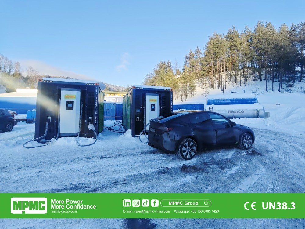
MPMC BCH Series mobile BESS charger
Why a Conventional Fast Charger Is Often Not Installable
A conventional DC fast charger converts incoming power and delivers it to the vehicle in real time. Its output is bounded by the supply behind it.
That produces three recurring obstacles in industrial parks.
The transformer may have no spare capacity. Adding a 400 kW charger to a site already near its contracted maximum demand requires a supply upgrade, which means a utility application, a connection charge and a construction programme.
The connection may be electrically weak. Long feeders, ageing distribution equipment and voltage variation can make high-power charging impractical even where the nominal capacity appears adequate.
The demand may be temporary or mobile. A charging point required at a laydown area for eighteen months does not justify permanent civil and electrical work.
In all three cases, the constraint is the connection, not the vehicles.
How the Battery-Integrated Architecture Changes the Constraint
Inserting storage between the supply and the vehicle separates input power from output power.
Stage
What happens
Effect on the site
Input
The unit draws AC from grid, generator set or solar, or DC from a fast-charging station on applicable models
Input can be sized to what the connection can actually sustain
Storage
Energy accumulates in the onboard battery between charging events
Total daily energy replaces peak power as the binding constraint
Output
The battery discharges at high power through CCS2 connectors
Charging speed is set by the unit, not by the connection
Parallel AC output
Applicable models supply site loads at the same time
The asset can serve as temporary site power as well as a charger
The constraint does not disappear. It moves. A unit can deliver high power only until its battery is depleted, and how quickly it returns to service depends on the input available for recharging. Sizing therefore starts with energy, not with charger output.
The MPMC BCH Range, Read for a Weak-Grid Site
For a weak-grid park, the AC input rating is as important as the DC output rating, because it determines what the site connection must support.
Model
DC charging output
Battery capacity at 25°C
AC input rated power
DC connectors
Weight
BCH-80-70
80 kW
70 kWh
Not applicable; 70 kW DC input
CCS2 260 A × 1
880 kg
BCH-275-200
150 kW
203.5 kWh
80 kW
CCS2 250 A × 2
2,800 kg
BCH-600-400
400 kW
407 kWh
280 kW
CCS2 350 A × 2
8,300 kg
BCH-800-600
600 kW
610.6 kWh
280 kW
CCS2 350 A × 2
15,000 kg
BCH-500-1000
500 kW
1,075 kWh
560 kW
CCS2 350 A × 2
19,800 kg
The BCH-275-200 illustrates the principle most clearly. It delivers 150 kW of DC charging from an 80 kW AC input, so the site connection needs to support roughly half the charging power. A conventional 150 kW charger would need the full 150 kW available at the point of connection.
Note that the larger models require substantial input themselves. The BCH-500-1000 lists a 560 kW AC input. On a genuinely weak connection, a large unit may need to be recharged over longer windows at reduced input rather than at its rated figure, which should be confirmed with MPMC for the specific installation.
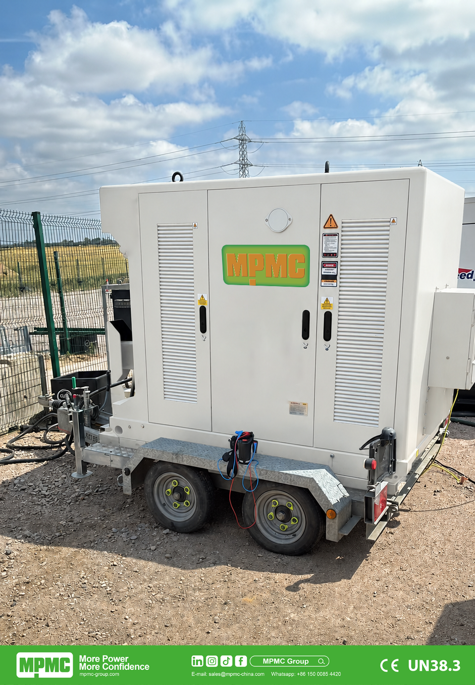
MPMC BCH-275-200
Model Selection Against Site Requirements
Site situation
Model to review first
Reason
Pilot deployment, a small number of light vehicles, or a compact site with a DC replenishment source available
BCH-80-70
Single gun, 880 kg, lowest site impact; recharges via DC input rather than AC
General weak-grid fleet charging with a modest available connection
BCH-275-200
150 kW output from an 80 kW input, dual CCS2 guns, trailer-mounted, listed as reaching full charge in approximately one hour via CCS2 DC input
Larger electric trucks or construction machinery
BCH-600-400
400 kW output with 407 kWh storage for higher energy per session
High-intensity charging where rapid energy transfer is required
BCH-800-600
600 kW output, 610.6 kWh storage, 1C charge and discharge performance
Central mobile charging and power hub with more than 1 MWh of reserve
BCH-500-1000
1,075 kWh storage in a 20 ft container format with 500 kW AC output available in parallel
Model designations do not correspond directly to output ratings, so selection should be made against the datasheet rather than the name.
Sizing: Work From Daily Energy
Step one. Count the vehicles and the energy each needs per charging session. Multiply by sessions per day. This gives total daily energy demand.
Step two. Establish how many vehicles must charge simultaneously. This sets the connector count and the required DC output, not the battery size.
Step three. Confirm the AC or DC input actually available at the intended location, and the hours per day it can be used. Input power multiplied by available hours gives daily replenishment before losses.
Step four. Compare demand with replenishment. If demand is higher, the options are a larger battery, a higher input, longer recharge windows or an additional unit.
For illustration only, a park with an 80 kW input available for 10 overnight hours can replenish in the order of 800 kWh per day before conversion losses. Whether that covers the fleet depends on the vehicles. Actual performance depends on the model, the input configuration and site conditions, and should be confirmed with MPMC for the proposed installation.
Vehicle and Connector Compatibility
Rated output is a ceiling. The vehicle’s battery management system sets the actual rate from its own pack voltage, state of charge, temperature and charging curve. A 400 kW charger connected to a vehicle that accepts 150 kW delivers 150 kW.
Three checks apply.
Connector standard. MPMC lists CCS2 as standard across the BCH range, with optional CCS1, GB/T and CHAdeMO for specific markets. Mixed fleets should be inventoried by connector before selection.
Voltage window. MPMC lists DC 50 to 1,000 V output on BCH-275-200 and above, and DC 200 to 1,000 V on the BCH-80-70. Construction machinery frequently operates at lower pack voltages than road vehicles.
Cable reach. Listed cable lengths are 7 m for the BCH-80-70, 3.5 m for the BCH-275-200 and 6 m for the larger models. This determines the parking layout and is a common source of on-site rework.
Using the Unit as More Than a Vehicle Charger
MPMC lists AC output on models from the BCH-275-200 upward, at 125 kW rated for the BCH-275-200, 200 kW for the BCH-600-400 and BCH-800-600, and 500 kW for the BCH-500-1000. Socket configurations listed include PowerLock and CEE outlets at a range of ratings.
For an industrial park this means the same asset can support temporary site power, welfare facilities or maintenance work when it is not charging vehicles. That improves utilisation, which is often what determines whether the investment is justified. The AC output configuration should be confirmed against the intended loads, since socket types and ratings differ by model.
Environmental and Safety Conditions
Parameter
BCH-80-70 and BCH-60-70
BCH-275-200 and above
Operating temperature
−20°C to +55°C, derating above 40°C
−20°C to +50°C, derating above 45°C
Maximum altitude
4,000 m, derating above 2,000 m
3,000 m, derating above 2,000 m
Cooling
LCAC
LCAC
Fire protection
Not listed
Aerosol (CE)
MPMC’s materials describe the BCH battery as a blade LFP pack with a high-strength structural architecture, tested for fire, water immersion, high-impact collision and crush, with a 65% larger heat dissipation area than conventional designs, 6.7°C temperature control precision and 390 Wh/L energy density. The sealed liquid-cooled pack is described as limiting dust ingress, which is the relevant characteristic for dusty industrial and construction environments.
Weight and container loading also affect siting. MPMC lists 4 units per 20 ft container for the BCH-275-200, 1 unit per 20 ft container for the BCH-600-400 and BCH-800-600, and a 20 ft GP format for the BCH-500-1000 at 19,800 kg. Ground bearing, lifting arrangements and road access should be checked against these figures.
Deployment and Remote Management
MPMC lists an EMS with 4G connectivity across the BCH range, OCPP 1.6 support on the BCH-80-70 and BCH-275-200 and above, and an open API for integration with third-party charging management systems. Optional RFID payment integration is listed for commercial fleet coordination. MPMC also states that full operational status is achievable within 24 hours of deployment.
OCPP support matters where the park already runs a charging management platform. Without it, the mobile unit sits outside the existing reporting and access control system, which creates a parallel process for billing and utilisation tracking.
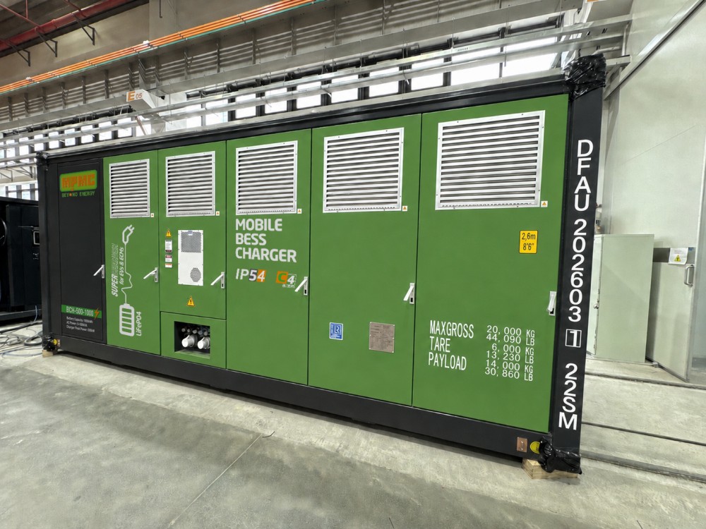
MPMC BCH Series mobile BESS charger-BCH-500-1000
Documented Deployments
Location
Configuration
Application
Norway
BCH Series, 2 MWh total; 500 kW and 1,000 kWh per unit; CCS2 output 360 kW / 400 A
Off-grid construction machinery charging without a diesel generator set
United Kingdom
BCH-275-200 × 8 units
Logistics port operations constrained by the local grid
Netherlands
BCH-275-200 and BCH-500-1000
Grid-connected EV charging for port and logistics operations
Netherlands
BCH Series, 500 kW / 1,000 kWh integrated unit; 1 MWh
Solar and storage grid-connected EV charging station
Site Preparation and Verification Checklist
Before deployment, the park should have the following in place.
• A verified electrical connection and protection arrangement for the input supply.
• A confirmed vehicle and machinery charging schedule, with daily energy and simultaneity figures.
• Designated parking and cable routing areas within the unit’s cable reach.
• Barriers or bollards to protect the unit against vehicle impact.
• Ground bearing and load-path checks against the unit’s weight.
• Lifting or towing arrangements appropriate to the model.
• Documented emergency shutdown procedures.
• Operator and emergency-response training for site staff.
• A defined plan for replenishing the onboard battery, including source and available hours.
Before ordering, the following should be confirmed in writing.
• Model-specific DC output, AC input rating and battery capacity from the current datasheet.
• Connector standard and DC voltage window against every vehicle type on site.
• Operating temperature and altitude limits against site conditions, including derating.
• Applicable compliance documents for the destination market, including IEC references and UN38.3 for battery transport.
• OCPP or API integration requirements with the existing charging management platform.
• Warranty terms. MPMC’s published policy lists 3 years or 1.6 MWh/kWh total output for the BCH-275-200, BCH-600-400, BCH-800-600 and BCH-500-1000, with a 5-year or 2.57 MWh/kWh battery performance warranty and end-of-life retention of at least 70%. The BCH-80-70 is listed separately at 1 year or 60 MWh total output, with a 3-year or 200 MWh battery performance warranty.
• Commissioning, service support, spare parts and remote diagnostic arrangements.
Frequently Asked Questions
Can a mobile charger remove the need for a grid upgrade? It can defer or reduce it. The unit allows charging to begin before reinforcement is complete, and in some cases a smaller permanent connection is sufficient afterwards. Whether the upgrade can be avoided entirely depends on the long-term fleet size and the site’s other loads.
How is the onboard battery recharged? MPMC lists AC input from grid, generator set or solar on applicable models, and CCS2 DC input for recharging from a fast-charging station. The BCH-275-200 is listed as reaching full charge in approximately one hour via DC input.
Does the unit need a permanent foundation? The BCH-275-200 is listed with a 3.5 t heavy-duty trailer and an integrated forklift hole for repositioning. Larger models are container-format and require lifting equipment. Ground bearing must be adequate in either case, but a permanent foundation is not generally required.
Can it charge vehicles and supply site loads at the same time? MPMC lists AC output alongside DC charging on models from the BCH-275-200 upward. The applicable socket configuration and simultaneous rating should be confirmed for the specific model.
How long does deployment take? MPMC states that full operational status is achievable within 24 hours of deployment. The site preparation listed above should be complete before the unit arrives, since that work usually takes longer than the commissioning itself.
https://www.mpmc-group.com/
MPMC Powertech Corp. -
AuthorPosts

- You must be logged in to reply to this topic.