

- This topic is empty.
-
AuthorPosts
-
2026-10-12 at 5:43 pm #12226
As semiconductor devices become more compact and operate under increasingly demanding conditions, temperature-dependent performance has become an important part of device characterization and reliability evaluation. Engineers often need to determine how an individual integrated circuit, power semiconductor, sensor, or electronic component responds to rapid changes in temperature while monitoring its electrical behavior.
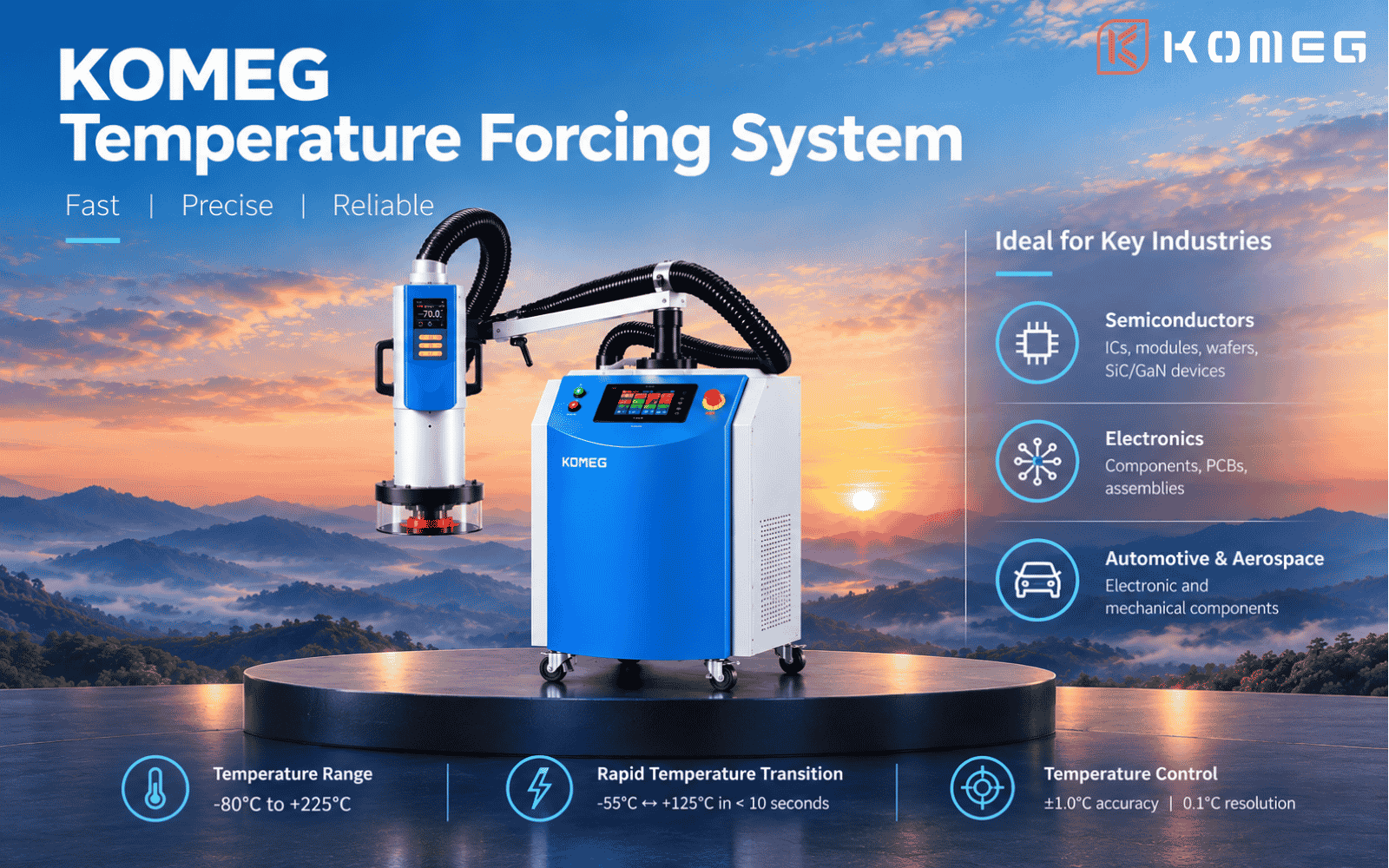
A Temperature Forcing System addresses this need by delivering controlled hot or cold airflow directly to a device under test (DUT). Instead of conditioning the entire test chamber, it creates a localized thermal environment around the selected component.
This approach is particularly useful for semiconductor characterization, electronic component testing, and investigations into temperature-related performance variations.
What Is a Temperature Forcing System?
A Temperature Forcing System is a thermal testing instrument designed to apply controlled temperature conditions to a specific device or test area. It typically combines a heating and cooling unit, an airflow delivery system, interchangeable nozzles, temperature sensors, and a control interface.
The conditioned airflow is directed toward the DUT, allowing engineers to change the local thermal conditions while the device remains connected to suitable measurement instruments.
Depending on the test setup, engineers can monitor electrical parameters, functional behavior, signal characteristics, or intermittent faults as temperature changes.
Unlike a conventional environmental chamber, which controls the conditions within a larger enclosed workspace, a Temperature Forcing System concentrates thermal stimulation on a selected target.
How Does a Temperature Forcing System Work?
The operating process generally involves four steps.
1. Generate controlled hot or cold airflow. The system establishes the required airflow temperature according to the selected test profile and operating limits.
2. Direct the airflow toward the DUT. A nozzle delivers the conditioned air to the target component. Nozzle position, distance, and airflow direction influence how heat is transferred to the device.
3. Monitor temperature and device behavior. Temperature sensors provide feedback at designated measurement points, while external test equipment records the DUT’s electrical or functional response.
4. Repeat the test under defined conditions. Engineers can apply different temperature setpoints or transitions to investigate performance changes, compare results, and reproduce suspected temperature-related faults.
The temperature transition of the equipment and the actual thermal response of the DUT are not necessarily the same. Package design, thermal mass, mounting conditions, airflow, and sensor placement can all affect how quickly the component reaches its intended temperature.
Key Applications in Semiconductor and Electronics Testing
Semiconductor IC Characterization
Integrated circuits can exhibit temperature-dependent changes in leakage current, timing behavior, electrical parameters, and functional performance. Localized thermal stimulation allows engineers to evaluate a selected device while monitoring relevant measurements.
This can be useful during device characterization, design validation, and troubleshooting when a particular IC needs to be investigated under controlled thermal conditions.
SiC and GaN Power Semiconductor Testing
Silicon carbide (SiC) and gallium nitride (GaN) devices are widely used in power conversion and high-efficiency electronic systems. Their electrical behavior and operating margins may vary with temperature.
A Temperature Forcing System can support component-level thermal evaluation when engineers need to observe device behavior across defined temperature conditions. The test configuration should reflect the device’s electrical limits, package characteristics, and intended application.
PCB and Electronic Component Evaluation
Printed circuit boards, sensors, connectors, power modules, and other electronic assemblies may contain individual components that respond differently to temperature changes.
Applying temperature directly to a selected component can help engineers investigate localized faults without imposing identical thermal conditions on the entire assembly. This can be valuable when a problem is difficult to reproduce during ordinary operation or conventional chamber testing.
Automotive and Aerospace Electronics
Automotive and aerospace electronics may be exposed to wide operating temperature ranges and demanding reliability requirements. Localized thermal testing can form part of a broader validation process for electronic components and subsystems.
The required test conditions should be established from the applicable product specifications, industry procedures, and project requirements. A Temperature Forcing System can support specific verification tasks, but the equipment alone does not establish compliance with a standard.
Temperature Forcing System vs. Environmental Test Chamber
Although both systems are used for thermal testing, they serve different purposes.
A Temperature Forcing System is generally appropriate when the test focuses on a particular component and engineers need to apply controlled hot or cold airflow while observing its behavior. It can provide flexibility for localized characterization and fault investigation.
An environmental test chamber is more suitable when an entire product, assembly, or sample group must be exposed to a controlled environment. Depending on its configuration, a chamber can also regulate humidity and support programmed environmental cycling.
The main selection question is therefore not which technology is universally better, but where the thermal condition needs to be applied.
Choose localized temperature forcing when the objective is to investigate a specific DUT. Consider an environmental chamber when the complete product or assembly must experience defined environmental conditions. Some laboratories use both approaches at different stages of development and validation.
What Should Engineers Consider When Selecting a Temperature Forcing System?
A suitable system should be selected according to the DUT, measurement method, and required test profile rather than temperature range alone.
Operating temperature range: Confirm that the required hot and cold setpoints fall within the system’s specified limits.
Temperature transition time: Check the exact temperature interval associated with the manufacturer’s transition-time specification. A stated equipment transition time should not be interpreted as a guarantee that every DUT will reach its target temperature within the same period.
Temperature control and measurement: Consider control accuracy, setpoint resolution, sensor type, sensor location, and the method used to verify the temperature at the DUT.
Airflow and nozzle configuration: Adjustable airflow and suitable nozzle options can help accommodate different package sizes and test geometries. The nozzle distance and direction should be controlled to improve repeatability.
Test equipment integration: Determine whether the system can be used with the required electrical instruments, probes, test fixtures, automated test equipment (ATE), or data acquisition setup. Compatibility depends on the specific test configuration.
Repeatability and documentation: Define the setpoints, transition profiles, dwell conditions, sensor locations, and measurement criteria. Consistent procedures help make results more comparable between test runs.
KOMEG Temperature Forcing System for Localized Thermal Testing
KOMEG provides environmental testing equipment for applications across semiconductor, electronics, automotive, and industrial sectors. Its Temperature Forcing System is designed to deliver controlled hot and cold airflow directly to the device under test, supporting localized thermal evaluation without requiring the entire test environment to be conditioned.
The system has an operating temperature range of -80°C to +225°C. For the specified interval between -55°C and +125°C, temperature transitions are rated at less than 10 seconds in both directions. It also offers temperature control accuracy of ±1.0°C, a setpoint resolution of 0.1°C, and continuously adjustable airflow from 5 to 24 SCFM.
A movable articulated arm and interchangeable nozzles provide flexibility when positioning the airflow around different test targets. The system does not require liquid nitrogen or CO₂ auxiliary cooling.
Actual DUT temperature response depends on the device, package, test fixture, airflow, nozzle position, and sensor arrangement. Engineers should verify the thermal conditions at the DUT when developing an application-specific test procedure.
More technical information is available on the KOMEG Temperature Forcing System product page.
Frequently Asked Questions
What is a Temperature Forcing System used for?
It applies controlled hot or cold airflow directly to a device under test. Common applications include semiconductor IC characterization, electronic component evaluation, localized thermal testing, and temperature-related fault investigation.
Can a Temperature Forcing System be used for semiconductor testing?
Yes. It can support temperature-dependent electrical and functional characterization of ICs, power semiconductors, modules, and other electronic devices when the test configuration is appropriate for the DUT.
Does temperature forcing replace an environmental chamber?
Not in every case. Temperature forcing is intended for localized thermal stimulation, while an environmental chamber conditions a larger enclosed volume. The choice depends on the test objective and whether the target is an individual component or the complete product.
Does a rapid equipment temperature transition mean the DUT reaches the target temperature just as quickly?
No. The equipment’s specified transition time and the DUT’s thermal response are different measurements. The DUT response depends on thermal mass, package construction, airflow, nozzle placement, and measurement location.
What information is needed to select a Temperature Forcing System?
Engineers should identify the required temperature range, transition profile, DUT dimensions, airflow needs, sensor arrangement, measurement equipment, and integration requirements. These details help determine whether a particular system is suitable for the intended application.
A Temperature Forcing System provides a practical option for localized thermal testing when engineers need to evaluate a selected electronic device under controlled hot and cold airflow. By considering temperature transition specifications, DUT response, airflow configuration, and measurement requirements together, engineering teams can develop more repeatable and informative test procedures.
For semiconductor and electronics applications, the most appropriate thermal testing solution is the one that matches the actual device, measurement objective, and required test conditions.
https://www.komegtek.com/product-category/temperature-forcing-system/
Temperature Forcing System -
AuthorPosts

- You must be logged in to reply to this topic.