

- This topic is empty.
-
AuthorPosts
-
2026-09-23 at 3:35 pm #11760
Quick answer: The JST VH connector is a 3.96mm pitch, single-row, through-hole wire-to-board crimp connector with a box-shaped leaf-spring contact and a large outer secure lock, rated 10A AC/DC (AWG #16, standard header) or 7A AC/DC (shrouded header), 250V AC/DC, −40 to +105°C, over 2 to 11 circuits. The KONNRA KR3961 is the cross-reference equivalent, and voltage, withstanding voltage, insulation resistance, durability and temperature all agree exactly. Two things do not: our contact-resistance ladder is exactly twice the original’s — 20mΩ maximum initially and 40mΩ maximum after test, against 10mΩ and 20mΩ in all four JST 3.96mm documents — and our 7A at AWG #18 is not the standard VH’s number. Underneath all of it: 3.96mm is a pitch, not a family.
I work on connector and harness programmes at KONNRA, so treat the disclosure as read. Everything below comes from manufacturer documents on both sides, and where they disagree I have said so rather than averaged them — including where JST disagrees with JST.
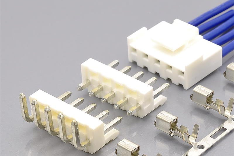
KONNRA KR3961 series VH 3.96 DIP wire-to-board crimp connector
Cross-reference and component pages: KR3961 cross-reference list · KR3961 straight wafer · KR3961 right angle wafer · KR3961 housing · KR3961 terminal
What the JST VH Actually Is
JST’s description: “This wire-to-board connector with a 3.96 mm pitch is commonly used in power supply circuits for a wide variety of electrical and electronic devices. It supports currents up to 10 A.”
Attribute JST published value Series / category VH connector; crimp style, wire-to-board PC board mounting Through-hole Mating direction / array Side entry, top entry; single-row Lock / retainer Secure lock (outer), secure lock (center); retainer Agency standards CSA, TÜV, UL Pitch 3.96mm Circuits 2, 3, 4, 5, 6, 7, 8, 9, 10, 11 Conductor size AWG #22, #20, #18, #16 — 0.33mm² to 1.25mm² Insulation O.D. φ1.7mm to φ3mm Remarks High-box type header available The contact is a box-shaped leaf spring — “a leaf-shaped design with excellent spring characteristics housed within a box” — and the lock is deliberately large and visible: “The large, highly visible outer-type housing with a strong lock ensures easy and secure insertion and removal.” The family also carries a second layer of variants: two housing shapes (N type with the lance exposed, M type with it molded into the resin), a retainer-compatible housing family, four standard headers plus a shrouded header, and two further products under the VH name at the same pitch. That is the reason a pitch-only search is dangerous.
The part-number map on the original’s side
Function JST series and part numbers Notes as published Contact, #22–#18 SVH-21T-P1.10.33–0.83mm², insulation φ1.7–3.0mm, 4,500 per reel, copper alloy tin-plated Contact, #20–#16 SVH-41T-P1.10.5–1.25mm², insulation φ1.7–3.0mm, 3,500 per reel, copper alloy tin-plated Housing, N type VHR-2N…VHR-11NContact lance exposed; PA, natural (white); 500–1,000 per bag Housing, M type VHR-2M…VHR-9MLances covered by resin, “further improving electrical safety” Housing, retainer-compatible VHRR-2N,VHRR-3N,VHRR-5N,VHRR-7N,VHRR-8N,VHRR-9NApplicable wire insulation narrows to φ1.7–2.2mm Retainer VHS-2V,VHS-3V,VHS-5V,VHS-7V,VHS-8V,VHS-9VPA (GF), natural (ivory); the set skips 4, 6, 10 and 11 Header, top entry B2P-VH…B10P-VHPost copper inlay, welded; base housing non-PBT/PA natural white; 100–1,000 per box Header, side entry B2PS-VH…B10PS-VHSame material set; moulded lead-in on the entry face Header, top entry with PBT B2P-VH-B…B11P-VH-BBase housing PBT (GF), natural white; the only variant that reaches 11 circuits Header, side entry with stopper S2P-VH…S5P-VHSide entry with stopper Header, shrouded B2P-VH-FB-B…B10P-VH-FB-BPost copper alloy tin-plated; base PBT (GF); “retainer mountable type cannot be used” Two details there decide whether a cross-reference will work, and neither is about electricity. The retainer-compatible housing narrows the wire window to “φ 1.7 to φ 2.2”, so a 2.8mm-insulation wire that suits the N-type housing falls outside it — and our cross-list publishes no retainer at all. And the shrouded header cannot be combined with that housing: “The housings that mate with the two position are the N-type and M-type. Please note that retainer mountable type cannot be used.”
What our cross-list covers, and what it does not
On the numbers our cross-reference page is correct: every JST series it names is a real VH number, and the orientation mapping is right, with
B(n)PS-VHmapped to our right-angle wafer andB(n)P-VHto our straight wafer. What it does not cover matters more:JST item In our cross-list Consequence N-type housings, VHR-2N–VHR-11NYes, 2P–11P Covered Contact SVH-21T-P1.1(#22–#18)Yes Covered Contact SVH-41T-P1.1(#20–#16)No The coarse-gauge contact has no mapped counterpart Top entry B(n)P-VH, side entryB(n)PS-VHYes, 2P–10P Covered Shrouded header B(n)P-VH-FB-BNo Not covered M-type housings VHR-nMNo Not covered Retainer-compatible housings VHRR-nNNo Not covered Retainers VHS-nVNo Not covered Side entry with stopper S(n)P-VHNo Not covered High-box type header No Not covered VR series (IDC) No Correctly not covered — different family For a customer using the coarse conductor (#20–#16), a retainer, or a shrouded header, the answer is not “we have an equivalent”, it is “we need to quote this specifically”.
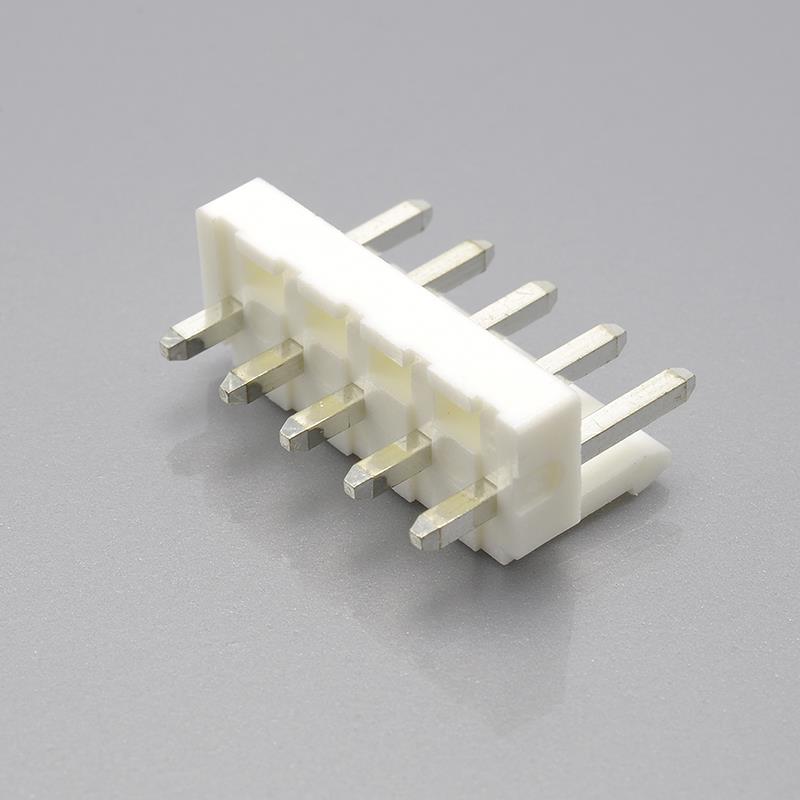
KONNRA KR3961 series VH 3.96 DIP straight type wafer, 3.96mm through-hole header
One Pitch, Four Different JST Terminations
The single most important thing to understand before cross-referencing anything at 3.96mm.
JST document Product Termination Current Voltage Temperature Contact resistance eVH.pdf VH connector (standard crimp) Crimp 10A AC/DC — AWG #16, standard header; 7A AC/DC — shrouded header 250V AC/DC −40 to +105°C initial 10mΩ max / after test 20mΩ max eVH-H.pdf VH connector, high box type Crimp 7A AC/DC (AWG #18); 10A AC/DC (AWG #16), 1 circuit only 250V AC/DC −25 to +85°C initial 10mΩ max / after environmental tests 20mΩ max eVH-QC.pdf VH connector, quick-connect type Insertion — no crimp 7A AC/DC, based on φ1.0mm solid wire 250V AC/DC −25 to +105°C initial 10mΩ max / after environmental tests 20mΩ max eVR.pdf VR connector — a different series IDC (insulation displacement) 7A AC/DC (AWG #18) 250V AC/DC −25 to +85°C initial 10mΩ max / after environmental tests 20mΩ max Four documents, one pitch, and two temperature ranges inside the VH name alone. The quick-connect type takes insulated solid copper wire of φ0.8mm to φ1.0mm with insulation φ1.1mm to φ1.3mm and has no crimp at all, following a four-step “strip wire / solid wire insertion / wire insertion completed / harness completed” process; the VR series is insulation-displacement, with contacts that “connect to the post with base at two separate points, in both the front and back areas”. Cross-reference by pitch alone and you can land on a crimp housing, a solid-wire socket, or an IDC socket — three parts that cannot use each other’s wire, tooling, or harness process. One trap follows: the VR series “can accommodate AWG #18 wire, which is rare for an IDC connector”, and 7A at AWG #18 is also exactly what our KR3961 publishes.
The Ratings Side by Side
Figure JST VH catalogue JST VH product page KONNRA spec §4.0 KONNRA component pages KONNRA cross-list Pitch 3.96mm 3.96mm 3.96mm 3.96mm (terminal page shows 3961mm) 3.96mm Voltage rating 250V AC/DC 250V AC/DC 250V AC/DC 250V 250V Current rating 10A (AWG #16, standard header) / 7A (AWG #16, shrouded header) 10A (AWG #16, standard header) / 7A (AWG #18, shrouded header) 7A (18AWG) 7A 7A implied Conductor size AWG #22 to #16; 0.33–1.25mm² AWG #22, #20, #18, #16; 0.33–1.25mm² AWG 18# to 22# 18#–22# — Insulation O.D. φ1.7 to φ3.0mm φ1.7 to φ3.0mm 2.8mm Max (no minimum) 2.8mm(Max) — Temperature range −40 to +105°C −40 to +105°C −40 to +105°C −40~105℃ — Contact resistance initial 10mΩ max; after test 20mΩ max — 20mΩ Max (initial, dry circuit) 20mΩ Max — Contact resistance after test 20mΩ max — 40mΩ Max (after durability, vibration, shock, heat, cold, humidity, salt spray, thermal shock) — — Insulation resistance 1,000MΩ min 1,000MΩ min 1,000MΩ Min at 500VDC 1000MΩ Min — Withstanding voltage 1,500VAC, 1 minute 1,500VAC, 1 minute 1,500V AC, 1 minute — — Durability — — 30 cycles at 10 cycles/min — — Applicable PC board thickness 1.6mm — not published — — Circuit count 2–11 2,3,4,5,6,7,8,9,10,11 §8.0 force table to 12 wafers 2P~7P, housing 2P~9P housings 2P–11P, wafers 2P–10P Agency standards CSA, TÜV, UL (VH); UL E60389 / CSA LR20812 / TÜV R75122 (high box) CSA, TÜV, UL UL E482542 UL E482542 RoHS/REACH Housing material PA, natural (white) PA, natural (white) PA66 UL94 V-0 PA66, UL94V-0 — Contact material Copper alloy, tin-plated Copper alloy, tin-plated Phosphor bronze or brass, tin plated over nickel Brass (wafer pin) Phosphor bronze (terminal) Header post Copper inlay, welded — Brass (solid) Brass — Solder tab — — None (correct for a through-hole part) — — Read the last four columns against each other, because the circuit count has four different answers inside our own documents; and the JST columns against each other, because the current rating has three different answers inside the original’s.
The Contact-Resistance Ladder Is Exactly Twice the Original’s
This is the finding of this round, and it is arithmetic rather than opinion. Both sides publish contact resistance as a pair — an initial value and a value permitted after testing — and each of our numbers is exactly double the corresponding original number.
Row JST requirement (all four 3.96mm documents) KONNRA requirement (PS-KR3961-01) Ratio Contact resistance, initial 10mΩ maximum 20mΩ maximum (§5.1, dry circuit, 20mV/100mA, EIA-364-23C) 2× Contact resistance, after durability (30 cycles) 20mΩ maximum 40mΩ maximum (§7.1) 2× Contact resistance, after vibration 20mΩ maximum 40mΩ maximum (§7.3) 2× Contact resistance, after shock 20mΩ maximum 40mΩ maximum (§7.4) 2× Contact resistance, after heat resistance 20mΩ maximum 40mΩ maximum (§7.5) 2× Contact resistance, after cold resistance 20mΩ maximum 40mΩ maximum (§7.6) 2× Contact resistance, after humidity 20mΩ maximum 40mΩ maximum (§7.7) 2× Contact resistance, after thermal shock 20mΩ maximum 40mΩ maximum (§7.8) 2× Contact resistance, after salt spray 20mΩ maximum 40mΩ maximum (§7.9) 2× Nine rows, one relationship, and it holds against all four original documents rather than one. The consequence sits on the top row: our initial requirement is identical to the original’s after-test requirement, so a KR3961 that just meets our published initial specification is at the limit the original permits after thirty mating cycles, vibration, thermal shock, humidity and salt spray. For dry-circuit or low-current work that is a specification gap rather than a product gap — ask for measured initial contact resistance rather than the requirement.
And the after-test rows are held to a different trigger
JST qualifies its 20mΩ after-test figure as “after environmental tests” in the high-box, quick-connect and VR catalogues and simply “After test” in the standard VH catalogue, while our 40mΩ applies after each named test individually — and after humidity we also require dielectric strength per §5.3 (1,500VAC for one minute) and insulation resistance of 100MΩ minimum. That post-humidity figure is the second place where we are looser: the original requires 1,000MΩ minimum, ours is 1,000MΩ generally (§5.2) but only 100MΩ after humidity (§7.7), and the same value appears in our 2.5mm, 2.54mm and 3.00mm specifications — so it reads as a family-template figure rather than a tested result for this series.
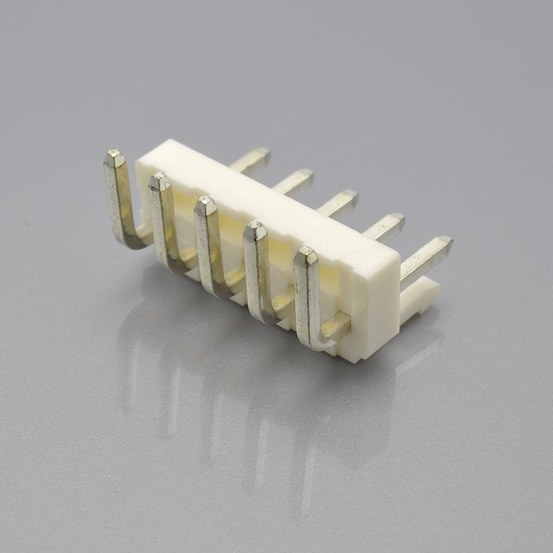
KONNRA KR3961 series VH 3.96 DIP right angle type wafer, side entry 3.96mm header
Where Our 7A Comes From, and Why It Is Not the Standard VH’s Number
JST publishes three different current figures for products it calls VH at this pitch, and the one we publish is not the standard connector’s.
Product JST current rating as published The conductor it is based on VH connector (standard crimp) 10A AC/DC “When using AWG #16 with the standard type header” VH connector (standard crimp) 7A AC/DC “When using AWG #16 with the shrouded type header” — per the catalogue VH connector (standard crimp) 7A AC/DC “When using AWG #18 with the shrouded type header” — per the product page VH connector, high box type 7A AC/DC (AWG #18); 10A AC/DC (AWG #16) one circuit only AWG #18 for the general case VH connector, quick-connect type 7A AC/DC “Based on φ1.0mm size solid wire” VR connector 7A AC/DC (AWG #18) AWG #18 KONNRA KR3961 7A (18AWG) AWG #18 Our 7A at AWG #18 has an exact precedent in JST’s own paperwork — but not in the standard VH. It is the published general rating of the VH high-box type and of the VR series, and the product page’s reading of the shrouded-header figure, while the standard VH’s headline rating is 10A and is explicitly built on AWG #16. JST does not agree with itself about the 7A shrouded-header conductor: the catalogue says AWG #16, the product page says AWG #18, and our own published 7A sits exactly on the disputed conductor. The risk is one of reading, not of performance — a buyer seeing “7A” on two datasheets concludes the parts agree, when the two figures are attached to different conductors in different products.
The gauge the original’s 10A is built on
Conductor JST VH KONNRA KR3961 AWG #16 (1.25mm²) supported — the basis of the 10A rating not supported AWG #18 (0.83mm²) supported supported, basis of the 7A rating AWG #20 (0.5mm²) supported supported AWG #22 (0.33mm²) supported supported Four conductor sizes on the original’s side, three on ours, and the one we give up carries the headline current. It is a terminal gap as well as a wire-range gap:
SVH-21T-P1.1covers AWG #22 to #18 andSVH-41T-P1.1covers AWG #20 to #16, and the coarse contact is a different part number with a different crimp geometry and reel quantity that has no counterpart in our published mapping.Five Ratings That Match Exactly
A guide that leads with the failures is no use to an engineer who simply needs to know whether the parts are interchangeable.
Item JST VH KONNRA KR3961 Verdict Voltage rating 250V AC/DC 250V AC/DC Match Withstanding voltage 1,500VAC for one minute, no breakdown or flashover 1,500V AC for one minute, no breakdown or flashover Match, including the pass criterion Insulation resistance 1,000MΩ minimum 1,000MΩ minimum at 500VDC Match Durability — (JST’s VH documents publish no cycle count) 30 cycles at 10 cycles per minute Not comparable — see the force section Temperature range −40 to +105°C including temperature rise −40 to +105°C Match PC board mounting Through-hole Through-hole only Match Row count Single-row Single-row Match The withstanding row matches at the level of the acceptance criterion, not just the number: JST applies 1,500VAC “between adjacent terminals and between terminals to ground” and ours states the same conditions in §5.3. The insulation-resistance row matches including the test voltage, because a supplier can pass a 1,000MΩ requirement at a lower applied voltage and the datasheet line looks identical.
Temperature: the second consecutive match, and it is worth naming
In earlier cross-references in this series — JST XH, Yeonho YH, JST EH, JST SM and JST SCN — the original’s range was −25 to +85°C every time and our −40 to +105°C looked like a house figure; the XA round was the first where the original’s own document agreed at −40 to +105°C, and VH is the second.
It matters here for a specific reason. JST’s own VH family contains a document that does say −25 to +85°C — the high-box type — and so does the VR series, so both figures are real JST 3.96mm figures and only one belongs to the crimp connector our cross-reference maps. And a caution attaches to our wider claim: we are wider than both siblings publish, so if the part being replaced is one of those, the limiting figure is the original’s.
The Wire Window: the Insulation Corridor Points the Other Way
JST VH KONNRA KR3961 Insulation O.D., standard housing φ1.7mm minimum to φ3.0mm maximum 2.8mm maximum — no minimum published Insulation O.D., retainer-compatible housing φ1.7mm to φ2.2mm not applicable — we publish no retainer Conductor size AWG #22 to #16 AWG 18# to 22# The original publishes a corridor. We publish a ceiling. At the top end we are 0.2mm tighter, since a wire with 2.9mm insulation is inside JST’s maximum and outside ours; at the bottom end we impose no floor at all, where the original requires 1.7mm, so a thin-wall wire of 1.2mm insulation would be rejected by the original and accepted by our published field — the opposite of the failure mode found in earlier rounds of this series. Ask for the insulation diameter as a number rather than inferring it from the gauge, and ask against the specific housing, because the same series has two insulation windows depending on whether a retainer is used.
The Force Ladder Is Ours Alone — and One Cell Does Not Fit
This is the one layer where the original publishes nothing at all: JST’s five documents publish no insertion force, no withdrawal force, no terminal retention force and no mating-cycle durability figure, so the 11-row ladder in our §8.0 stands alone, and it contains one value that does not follow the pattern the other thirty do.
Circuits I.F. maximum (kgf) Step R.F. minimum, initial (kgf) R.F. minimum, 30th cycle (kgf) 2 3.00 — 1.00 0.80 3 3.50 +0.50 1.20 0.90 4 4.00 +0.50 1.40 1.00 5 4.50 +0.50 1.60 1.10 6 5.00 +0.50 1.80 1.20 7 5.50 +0.50 2.00 1.30 8 6.00 +0.50 2.20 1.40 9 6.50 +0.50 2.40 1.50 10 7.00 +0.50 2.60 1.60 11 7.50 +0.50 2.80 1.70 12 8.50 +1.00 3.00 1.80 - Insertion force maximum = 2.50 + 0.50n for circuits 2 through 11 — then the 12-circuit row steps by 1.00kgf instead of 0.50, landing at 8.50 rather than the 8.00 the progression predicts.
- Withdrawal force minimum at first mate = 0.60 + 0.20n, holding for every row from 2 to 12.
- Withdrawal force minimum at the 30th cycle = 0.60 + 0.10n, also holding for every row from 2 to 12.
I cannot tell from the document whether the 12-circuit value is a typographical carry or a deliberate extra margin, and I am not going to guess — it is the only cell that breaks its own progression, so if your design uses a 12-circuit KR3961 and insertion force is constrained, confirm it in writing. The ladder also models a real decay, which is worth crediting: at 12 circuits the guaranteed minimum after 30 cycles is 1.80kgf, or about 17.7N, against an insertion-force maximum of 8.50kgf. On terminal-level figures our specification is unambiguous and the original’s is silent — terminal insertion force 1.5kgf (14.7N) maximum (§6.2), terminal-to-housing retention 3.0kgf (29.4N) minimum (§6.3) and pin retention 2.0kgf (19.6N) minimum (§6.4) at 25.4 ± 3 mm per minute and EIA-364-13D — and these are capabilities we document, not claims of superiority.
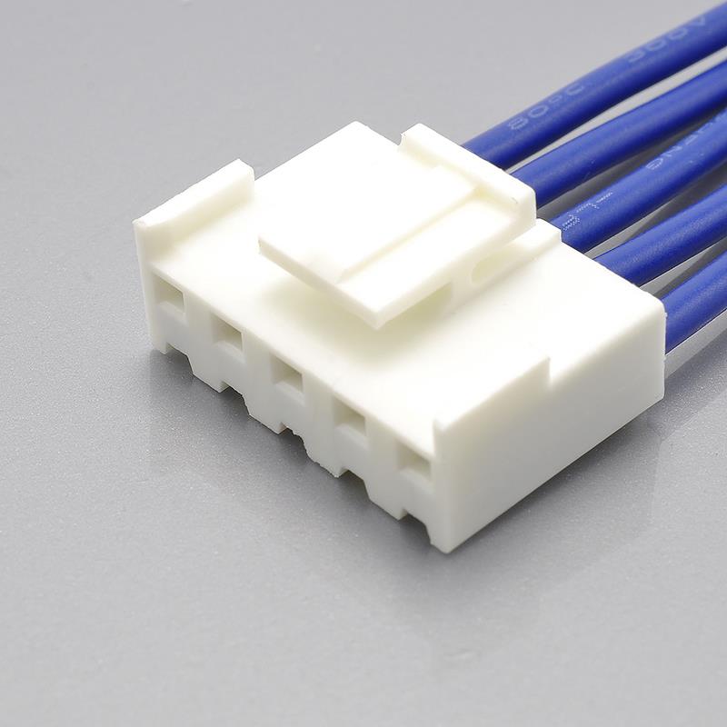
KONNRA KR3961 series VH 3.96 housing for the JST VH 3.96mm wire-to-board pattern
Materials: the Fork JST Closes and We Leave Open
This is the most consequential materials difference in this guide, and it is not about which plastic is used. JST’s VH high-box catalogue states: “Do not branch in parallel current which exceeds the rated current. If branched in parallel, current imbalance or other problems may develop. If it is absolutely necessary to branch such a large current in parallel, be sure to use contacts made of phosphor bronze.” One material is named as the requirement for a specific duty, and brass is by implication excluded from it.
Our specification writes the terminal material as a choice. §3.0 states “Phosphor bronze or Brass, Tin plated over nickel,” and §2.0 lists two terminal part numbers,
T39610PT0101AandT39610BT0101A, differing in a single letter. The obvious reading is that the letter selects the material, but the specification does not say which is which, and the cross-list maps onlyT39610PT0101A, toSVH-21T-P1.1, leaving theBTvariant with no published counterpart or description. Three questions belong in writing before a quotation:- Which of the two terminal part numbers is phosphor bronze and which is brass?
- Is the brass option acceptable for parallel branching at rated current, given that the original names phosphor bronze for that duty?
- Why does the cross-list map only one of the two?
Carefully stated, this is a documentation gap rather than a demonstrated defect — we may well ship the phosphor bronze part by default, and the cross-list suggests we do.
Component JST KONNRA Housing PA, natural (white) — flame-retardant grade referred to the overseas-standards list PA66, UL94 V-0 Retainer PA (GF), natural (ivory) not published Contact, crimp Copper alloy, tin-plated Phosphor bronze or brass, tin plated over nickel Header post, standard Copper inlay, welded Brass, solid Header post, shrouded Copper alloy, tin-plated not published Header base housing Non-PBT/PA natural white, or PBT/PBT (GF) natural white PA66, UL94 V-0 Solder tab not applicable None Two points in our favour: we publish a flammability grade where the original’s catalogue refers elsewhere for it, and a nickel barrier under the tin where the original says only “copper alloy, tin-plated” — the standard defence against the copper-tin intermetallic growth that drives contact resistance up over thermal ageing, though whether JST uses one without stating it I cannot determine from the public documents. Two construction differences deserve naming rather than scoring: JST’s standard post is a “copper inlay, welded” composite rather than a solid pin, and JST offers base housings in both non-PBT/PA and PBT/PBT (GF) where we publish PA66 throughout.
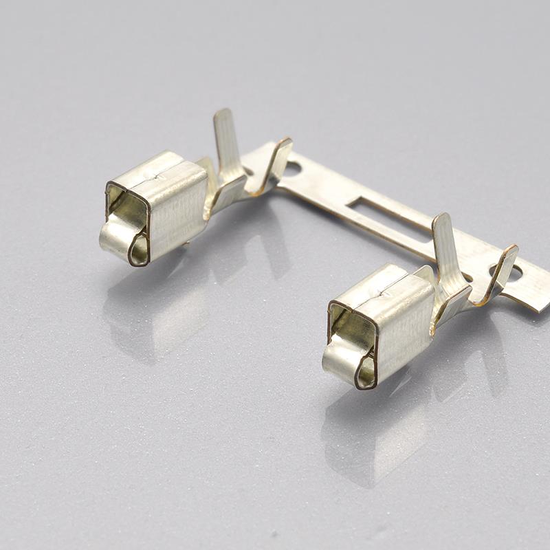
KONNRA KR3961 series VH 3.96 crimp terminal for the JST VH pattern
What the Original Publishes That We Do Not
Every item below is a figure or a document JST publishes for this series and ours does not; the response to each is a document request, not an assertion.
- Agency registrations beyond UL — JST lists CSA, TÜV and UL and prints UL Recognized E60389, CSA Certified LR20812, TÜV R75122; we publish UL E482542 only.
- Applicable PC board thickness — 1.6mm for the standard, high-box and quick-connect types and 0.8mm to 1.6mm for the VR series; we publish none.
- The PC board layout — JST notes that “tolerance for the PCB hole pitch shall be ±0.05 and shall not accumulate”; we publish no layout and no hole-pitch tolerance.
- The crimp tooling, named — the AP-K2N machine, the MKS-L applicator and the APLMK SVH21-11 / APLMK SVH41-11 applicators with dies; we publish no tooling identification.
- Package quantities — 4,500 and 3,500 contacts per reel, 500 to 1,000 housings per bag, 100 to 1,000 headers per box; our own package specification carries no extractable text layer.
- The M-type housing, the retainer and the shrouded header — all three absent from our published range, and the retainer changes the applicable wire window.
- The high-box type, header and mounting envelope — 21.3mm mounting height (18.6mm for a single circuit) and 9.2mm thickness (8mm single circuit), “for use specifically with resin coated (‘potted’) PC board”, with its vibration, prying, microcurrent and micro-voltage circuit claim.
- The ordering-code grammar — a model-number allocation including colour suffixes (natural, black, red, blue, green, orange, yellow, pink, grey, tomato red), so a non-standard colour or an 11-circuit top-entry PBT header has no route from our documents to a part number.
Where Our Own Documents Disagree With Each Other
A cross-reference is only as good as the weaker of the two catalogues, and ours has internal contradictions that a careful buyer will find.
1. Four different circuit ranges for the same series.
Source Published range Cross-list page, housings 2P to 11P Cross-list page, wafers 2P to 10P Housing component page 2P to 9P Wafer component pages 2P to 7P Product specification §8.0, force table 2 to 12 circuits Because the original’s housings run to 11 circuits and its top-entry PBT header to 11 as well, the cross-list’s 2P–11P is the correct answer and the two component pages are the ones to reconcile. The terminal page’s pitch field also reads “3961mm” where the value should be 3.96mm, and both wafer pages name “KR3960 Series” rather than KR3961.
2. Our component pages publish only one half of the contact-resistance story, showing “Contact Resistance: 20mΩMax” without stating that this is the initial, dry-circuit value — an asymmetry that hides the most important comparison in the family. The “Compatible” field is equally coarse: all four pages read “Compatible: VH Series”.
3. The cross-list answers a standards question with a compliance question — its Standard column reads RoHS/REACH on every row, with no column for CSA, TÜV or UL — and publishes no ratings at all, so a buyer arriving at the KR3961 landing page from search gets part numbers and no electrical specification.
4. One existing page on the site contradicts this whole guide, and it is the page most likely to be found first — an article titled “How to Solve VH Connector Compatibility Issues: Expert Advice”:
Claim on that page What the original publishes “Most VH connectors are rated for 5 amps and 250 volts” 10A AC/DC at AWG #16 on the standard header; 7A AC/DC on the shrouded header. There is no 5A rating anywhere in the VH documents. “Most VH connectors can operate between -25°C and 85°C” The standard VH is −40 to +105°C. −25 to +85°C is the high-box type and the VR series. “Some VH connector models come with waterproof designs that meet IP ratings” No JST VH document publishes an IP rating or a sealed variant. The temperature claim now contradicts our own product specification.
The Cross-Reference Map
KONNRA component JST series KONNRA part number Positions Housing, N type VHR-2N…VHR-11NH396101**0101A2–11 (cross-list) / 2P~9P (component page) Terminal, phosphor bronze SVH-21T-P1.1(#22–#18)T39610PT0101A— Terminal, second variant no mapping published T39610BT0101A— Straight wafer, DIP 180° (top entry) B2P-VH…B10P-VHC3961VD1**01T0101PA2–10 (cross-list) / 2P~7P (component page) Right angle wafer, DIP 90° (side entry) B2PS-VH…B10PS-VHC3961RD1**01T0101PA2–10 (cross-list) / 2P~7P (component page) Coarse-gauge contact SVH-41T-P1.1(#20–#16)none published — Housing, M type VHR-2M…VHR-9Mnone published — Housing, retainer-compatible VHRR-2N…VHRR-9Nnone published — Retainer VHS-2V…VHS-9Vnone published — Side entry header with stopper S2P-VH…S5P-VHnone published — Top entry header, PBT, 11 circuits B11P-VH-Bnone published — Shrouded header B2P-VH-FB-B…B10P-VH-FB-Bnone published — High-box type — none published — Quick-connect type — none published — Every JST number there is a real VH number, and on the mainstream half the mapping is complete and correct; the uncovered rows are coverage gaps rather than errors of identification. Two practical notes. Orientation first: our cross-list maps the original’s side-entry header to our right-angle wafer and its top-entry header to our straight wafer — correct, but two different vocabularies for the same geometry. Then the terminal fork: until engineering says which variant carries which material and which duties, quote the mapped part number —
T39610PT0101A— rather than choosing on the basis of a part-number letter.Applications Where the 3.96mm Pattern Is Used
JST’s published scope is one sentence: “This wire-to-board connector with a 3.96 mm pitch is commonly used in power supply circuits for a wide variety of electrical and electronic devices.”
Variant Application scope as published by JST Standard VH Power supply circuits in a wide variety of electrical and electronic devices High box type “For use specifically with resin coated (‘potted’) PC board”; for vibration, prying, microcurrent and micro-voltage circuits Quick-connect type Insulated solid copper wire installation, four-step process, no crimp VR series Daisy chain through connections and end connections, depending on the circuit design Note what is absent: JST publishes no market or application matrix for VH, unlike the five-market table Molex publishes for its comparable 3.00mm family. Power supply circuits make the current rating the binding constraint — the row where our wire window costs us AWG #16 — and through-hole, unsealed construction means neither side publishes an IP rating. Micro-current work appears only in the high-box scope note, precisely where contact resistance moves to the front of the queue, and daisy-chain work belongs to the VR series rather than the crimp VH.
We supply the KR3961 as components, as crimped housing assemblies, and as finished harnesses, so if you need a harness rather than components, ask for the drawing package with the quotation — crimp geometry, pull-out, retention and board layout are exercised on the harness side rather than on the component datasheets.
Sourcing: What Procurement Teams Ask
Which half of the pair am I buying? VH is a housing-and-terminal system on the wire side and a header on the board side, and our cross-list covers both — so order the housing set, the terminals and the wafer as three separate line items, plus two more if you need both wafer orientations.
Is the wire I already use inside the window? AWG 18# to 22#, with our published insulation field giving 2.8mm maximum and no minimum. Two exclusions catch people: AWG #16 is outside the range entirely, and a thin-wall wire below 1.7mm insulation is accepted by our published field but not by the original’s.
What is the minimum order quantity and the lead time? Connector production lead time is typically 2 to 4 weeks and wiring harness lead time typically 3 to 4 weeks, with complete connector set samples within 45 days — and samples are the right first step, because terminal material, exact circuit range and measured rather than specified contact resistance are faster to confirm on a sample than in a drawing.
What documentation arrives with the parts? Ask for the product specification, the package specification, the series drawing and the component drawing for each part number, then for the two documents we do not publish: the PCB layout with the hole-pitch tolerance, and the applicable board thickness.
Can you hold the specification? Reference the part number and the specification revision — PS-KR3961-01 revision A1 — and name the terminal material and the housing circuit count, because our Remark section states: “Any change or revision for the product specification will not be announced in advance.”
What about the second source? On voltage, withstanding voltage, insulation resistance, durability and temperature the match is exact; on contact resistance and the coarse-conductor current rating we are measurably behind the original’s published requirements, so a design that is contact-resistance-limited or runs at 8-10A per circuit needs those two rows answered first.
The Five Questions I Would Ask Us, In This Order
Ordered by what is cheapest to answer, not by what is easiest.
1. “Which of your two terminals is phosphor bronze, and which is brass?” The specification lists “phosphor bronze or brass” with two part numbers differing in one letter, and the cross-list maps only
T39610PT0101A. First, because the wrong answer has a failure mode rather than a specification gap.2. “My circuit runs at 9A and I use AWG #16. Do you cover it?” No — AWG #16 is outside our published wire range of 18# to 22#, while the original rates 10A on that conductor. It is a coverage limit rather than a quality difference, and it decides whether a cross-reference is possible at all.
3. “My wire has 1.5mm insulation. Does that fit?” Our published field does not exclude it, but the original requires a minimum of φ1.7mm, and with a retainer the window narrows to φ1.7–2.2mm.
4. “What is the measured initial contact resistance, not the requirement?” Our §5.1 requires 20mΩ maximum, exactly the original’s post-test limit, while the original’s own initial requirement is 10mΩ.
5. “How many circuits can you actually supply?” Our own documents give four answers — 2P~7P, 2P~9P, 2P–10P and 2–12 — and the original’s housings run to 11 circuits, so ask for the range against the specific part number.
A sixth: “What does the cross-list not cover for my build?” The uncovered items are AWG #16 contacts, M-type housings, retainer-compatible housings, retainers, the side-entry stopper header, the 11-circuit PBT header and the shrouded header — a quotation rather than a substitute for anyone using them.
Engineer’s Pre-Release Checklist
Nine checks, in the order the failures actually happen.
- Conductor. Confirm AWG 18# to 22#; if your design uses AWG #16 for the 10A capability this cross-reference does not cover it.
- Current at your conductor. Ours is 7A at 18 AWG; the original’s is 10A at 16 AWG on the standard header, with its 7A shrouded-header figure attributed to AWG #16 in the catalogue and AWG #18 on the product page.
- Wire insulation. Ours is 2.8mm maximum with no minimum; the original’s is φ1.7 to φ3.0mm, narrowing to φ1.7–2.2mm with a retainer-compatible housing — so a wire between 2.2mm and 2.8mm is acceptable to us and not usable on the original if a retainer is used.
- Contact resistance. Ours is 20mΩ maximum initially and 40mΩ maximum after test; the original’s is 10mΩ initially and 20mΩ after test. If your design is not current-limited, this decides equivalence.
- Post-humidity insulation resistance. Our §7.7 requires only 100MΩ minimum against our own headline of 1,000MΩ and the original’s 1,000MΩ.
- Voltage and dielectric. Both sides are 250V and both test at 1,500VAC for one minute with no breakdown or flashover — no further work needed.
- Temperature. Ours is −40 to +105°C and matches the standard crimp VH exactly; if the original part is a high-box type or a VR series part, its own range is −25 to +85°C and the limiting figure is the original’s.
- Terminal material. Ask which of the two terminal variants you are quoted, and confirm it against JST’s statement that phosphor bronze contacts are required where high current must be branched in parallel.
- Circuit count and material grade. Confirm the circuit range against the exact part number rather than our component pages, and confirm the PA66 UL94 V-0 housing grade.
Frequently Asked Questions
What is a JST VH connector?
A 3.96mm pitch, single-row, through-hole wire-to-board crimp connector rated 10A AC/DC with AWG #16 on the standard header, 7A AC/DC with the shrouded header, 250V AC/DC, −40 to +105°C, 1,000MΩ minimum insulation resistance and 1,500VAC for one minute, over 2 to 11 circuits, for conductors AWG #22 to #16 (0.33–1.25mm²), insulation φ1.7 to φ3.0mm and board thickness 1.6mm.
Is the JST VH the same thing as 3.96mm pitch?
No. JST sells four different products at 3.96mm: the standard crimp VH (−40 to +105°C), the VH high-box type (−25 to +85°C, for resin-potted boards), the VH quick-connect type (−25 to +105°C, for insulated solid wire, no crimp) and the VR series (insulation-displacement, 7A / AWG #18, −25 to +85°C). They do not share wire, tooling or harness process.
What is the difference between the VH and the VH high-box type?
The mounting envelope, the temperature range and the intended board. The high-box type has a 21.3mm mounting height (18.6mm for a single circuit) and 9.2mm thickness (8mm single circuit), is “for use specifically with resin coated (‘potted’) PC board”, and rated −25 to +85°C, with 7A at AWG #18 and 10A at AWG #16 limited to one circuit only.
Are VH and VR the same series?
No. VR is a separate JST series at the same 3.96mm pitch, an IDC (insulation displacement) connector whose contacts “connect to the post with base at two separate points, in both the front and back areas” — rated 7A AC/DC at AWG #18, 250V, −25 to +85°C, for conductors AWG #26 to #18 and board thickness 0.8mm to 1.6mm, and it supports daisy-chain through connections.
What is the KONNRA equivalent of the JST VH?
The KR3961 series — housing, crimp terminal and both wafer orientations in PA66 UL94 V-0, with brass wafer contacts tin plated over nickel and a housing range our cross-list gives as 2 to 11 positions — rated 250V AC/DC, 7A at AWG #18, −40 to +105°C, 20mΩ maximum, 1,000MΩ minimum at 500VDC and 1,500VAC for one minute.
What current and voltage does the VH carry, and what does the KR3961 carry?
JST: 10A AC/DC with AWG #16 on the standard header, 7A AC/DC on the shrouded header, at 250V AC/DC. KONNRA: 7A at AWG #18, at 250V AC/DC. The voltage row matches exactly; the current row matches only at the gauge we both support, and JST’s catalogue and product page disagree on the 7A shrouded-header conductor: AWG #16 versus AWG #18.
What wire gauge does the JST VH accept?
AWG #22 to #16 — 0.33mm² to 1.25mm² — in four steps: #22, #20, #18 and #16, with
SVH-21T-P1.1covering AWG #22 to #18 andSVH-41T-P1.1covering AWG #20 to #16. Our KR3961 documents AWG 18# to 22# — three of the four original sizes — and the missing one, AWG #16, is the conductor the original’s 10A rating is built on.What insulation diameter does it accept?
JST publishes a corridor: φ1.7mm to φ3.0mm, narrowing to φ1.7mm to φ2.2mm with the retainer-compatible housing. Our specification publishes only a maximum, 2.8mm, with no minimum — 0.2mm tighter at the top and silent where the original sets a 1.7mm floor.
What is the contact resistance of the VH?
Initial 10mΩ maximum; after test 20mΩ maximum — the same pair in every JST 3.96mm document. The KR3961 requires 20mΩ maximum initially and 40mΩ maximum after test, exactly twice the original’s on both rows, so our published initial requirement equals the original’s post-test limit.
What are the insulation resistance and withstanding voltage?
Both 1,000MΩ minimum, and both 1,500VAC for one minute with no breakdown or flashover. Ours names the test voltage — 500VDC for one minute between adjacent contacts per EIA-364-21B — and the one departure is post-humidity insulation resistance: 100MΩ minimum under §7.7.
What is the operating temperature range?
−40 to +105°C, including temperature rise from applied current, and the KR3961 publishes the same — an exact match against the standard crimp VH. The high-box type and the VR series both publish −25 to +85°C, so against those variants our figure is the more generous claim, not the matching one.
How many circuits does the VH come in?
JST: 2 to 11 circuits. The N-type housings run to 11, the M-type to 9, the top-entry PBT header
B11P-VH-Bis the only header that reaches 11, and retainers cover 2, 3, 5, 7, 8 and 9 circuits, skipping 4, 6, 10 and 11. Our own documents give four different ranges — 2P–11P and 2P–10P on the cross-list, 2P~9P on the housing page, 2P~7P on the wafer pages and 12 in the force table.Does the KR3961 have a retainer, a shrouded header or a high-box type?
No — none of the three. The original publishes a full retainer family (
VHS-2VthroughVHS-9V) with retainer-compatible housings whose insulation window narrows to φ1.7–2.2mm; a shrouded header family (B2P-VH-FB-Band others) that cannot be used with the retainer housing; and the high-box type for potted boards. Our cross-list stops at the mainstream crimp VH.What materials are used?
JST: housing PA, natural (white), flame-retardant grade referred to its overseas-standards list; contacts copper alloy, tin-plated; standard header post copper inlay, welded; base housings in non-PBT/PA or PBT/PBT (GF). KONNRA: housing PA66 UL94 V-0; terminal “phosphor bronze or brass, tin plated over nickel”; wafer base PA66 UL94 V-0, wafer contact and pin brass, tin plated over nickel. The original names phosphor bronze where high current must be branched in parallel, which our “phosphor bronze or brass” field leaves open.
What UL, CSA and TÜV files does the VH carry?
JST’s VH product page lists CSA, TÜV and UL, and its high-box catalogue prints UL Recognized E60389, CSA Certified LR20812, TÜV R75122. Our component pages publish UL E482542 only — no CSA registration and no TÜV mark.
Is the KR3961 a drop-in replacement for the JST VH?
On voltage, dielectric strength, insulation resistance, durability, temperature and the through-hole single-row construction the match is exact and a drop-in evaluation is credible. On three points the answer is no: the contact-resistance ladder is exactly twice the original’s on both rows, AWG #16 is outside our published wire range while the original’s 10A rating depends on it, and post-humidity insulation resistance is 100MΩ against the original’s 1,000MΩ. Treat it as a drop-in for a ≤250V, ≤7A, 18–22 AWG application and as an evaluated alternative anywhere else.
How long does it take to get samples?
Complete connector set samples within 45 days, with connector production lead time typically 2 to 4 weeks and wiring harness lead time typically 3 to 4 weeks. Say which half you need, and include your conductor size, insulation diameter and working current.
Start Your Cross-Reference Check
KONNRA supplies the KR3961 series as individual components, crimped housing assemblies or complete wire harnesses, with customisation available for application-specific requirements.
- Request a quote or a sample — configuration for your circuit count, conductor and orientation; complete connector set samples within 45 days
- Request the terminal material in writing — which of the two terminal part numbers is phosphor bronze and which is brass
- Request the measured initial contact resistance — our requirement is 20mΩ maximum; the original’s initial requirement is 10mΩ
- Request the board-side and tooling data — JST publishes 1.6mm board thickness and a ±0.05 non-accumulative hole-pitch tolerance; we publish neither
- Request the 12-circuit insertion force clarified — §8.0’s twelve-circuit row breaks the table’s own 2.50 + 0.50n progression
- Request the specification revision — PS-KR3961-01 revision A1, with the terminal material and circuit count named in the purchase order
- Submit a drawing for review — we will flag any specification mismatch before you commit tooling or a board respin
Contact KONNRA Electronics: (86)-769-85449875 · info@konnra.com · No.6 Nanchang South Road, Chijiao, Wangniudun, Dongguan, Guangdong, China
Sources and method. Every figure here comes from a manufacturer document, and where two documents disagree — including two from the same manufacturer — both are printed rather than averaged. JST: the VH series page (series 262), the VH catalogue
eVH.pdf, the high-box catalogueeVH-H.pdf, the quick-connect catalogueeVH-QC.pdfand the VR catalogueeVR.pdf. KONNRA: PS-KR3961-01 revision A1 (2022/2/26, 7 pages), the cross-reference page, the four component pages (straight wafer, right angle wafer, housing, terminal), and the series and component drawings (KR3961-Series-Drawing, KR3961-H, KR3961-T_2, KR3961-WR-DIP_3, KR3961-WV-DIP_4). The KR3961 drawings are vector PDFs with no text layer, so no dimension here was taken from a drawing, and the package specification carries no extractable text, so none of its contents are quoted.https://konnra.com/jst-vh-3-96-connector-complete-guide/
Dongguan Konnra Electronics Co., Ltd -
AuthorPosts

- You must be logged in to reply to this topic.