

- This topic is empty.
-
AuthorPosts
-
2026-09-23 at 3:43 pm #11766
A 3.00mm cross-reference for engineers who have to sign the drawing — a 250V rating against a 600V family, a wire window covering three of the original’s seven rated sizes, and every place our own documents disagree
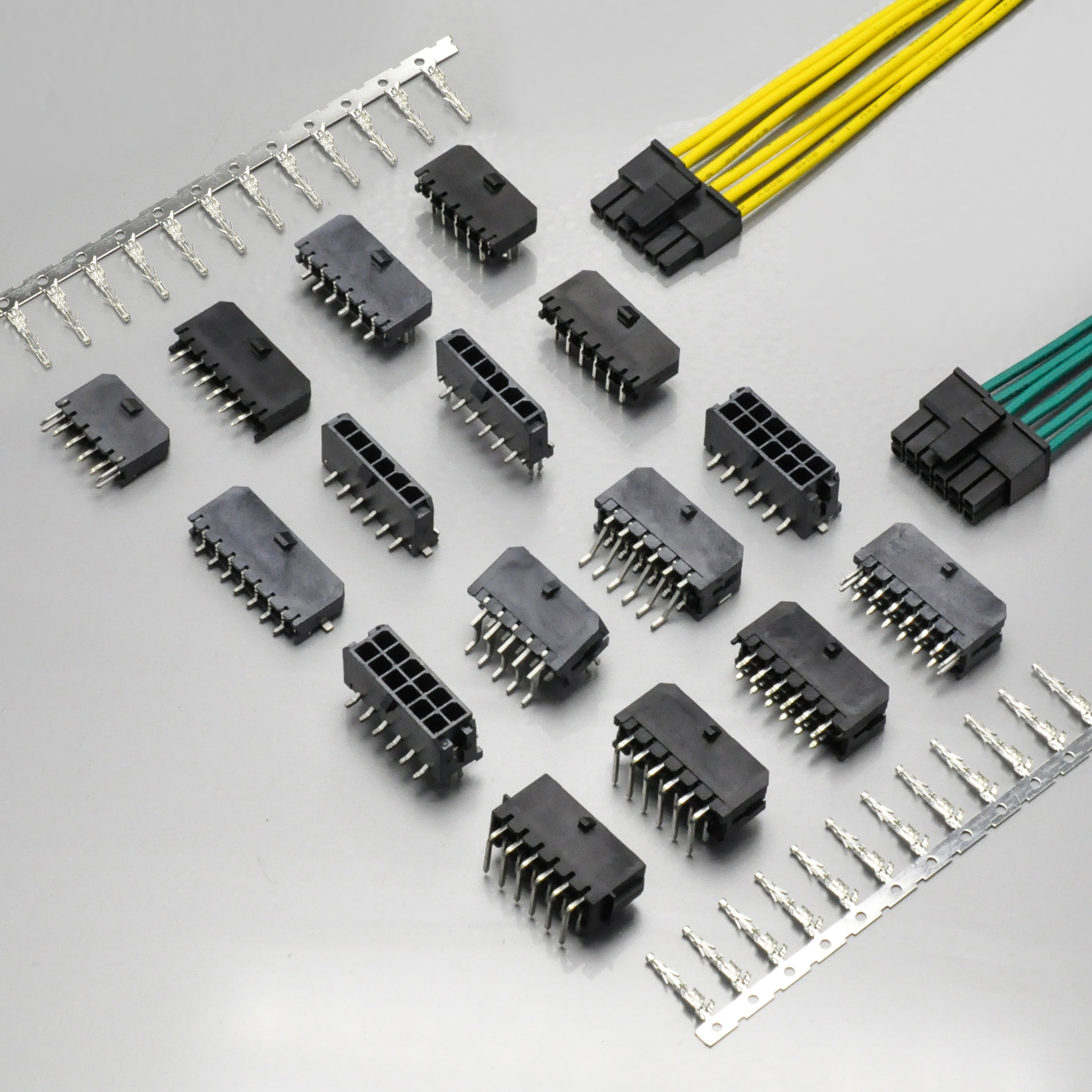
KONNRA KR3000 series Micro-Fit 3.0 3.00mm wire-to-board crimp connector
KR3000 Series product page · Wire-to-board version · Wire-to-wire version
Quick answer: The Molex Micro-Fit 3.0 — catalogued in Asia as MX3.0 — is a 3.00mm pitch, single-row and dual-row crimp family doing both wire-to-board and wire-to-wire, holding by a positive friction lock with an optional terminal position assurance (TPA) device, rated by Molex at 600V, up to 10.5A, from −40 to +105°C with tin or −40 to +125°C with gold, in 2 to 24 circuits. The KONNRA KR3000 is the cross-reference equivalent, and here the mechanical layer lines up most closely: Molex publishes 14.7N maximum contact insertion and 24.5N minimum retention, and we publish 1.5kgf (14.7N) and 2.5kgf (24.5N) — the same two numbers in a different unit. Molex publishes 8N maximum insertion and 2.4N minimum withdrawal per circuit; our per-circuit ladder gives 0.80kgf (7.85N) and 0.25kgf (2.45N), inside the original’s window at both ends. Four more rows match exactly: contact resistance 10mΩ maximum, insulation resistance 1,000MΩ minimum at 500VDC, durability 30 mating cycles, and humidity 96 hours at 40°C and 90–95% R.H. Where we are genuinely behind is voltage — 250V against the original’s 600V agency rating — and the wire window, which covers three of the seven conductor sizes in the original’s own derating table.
I work on connector and harness programmes at KONNRA, so treat the disclosure as read. Everything below comes from manufacturer documents on both sides, and where they disagree I have said so rather than averaged — including where the original disagrees with itself: Molex’s own test summary reports 19.95mΩ against its own 10mΩ limit, and Molex publishes two different minimum pull-out figures for 24 AWG wire in two documents.
What the Micro-Fit 3.0 family actually is — and its part-number map
Micro-Fit is one of Molex’s largest families, and it is not one connector — it is a family of product lines built on a shared 3.00mm contact system. Molex’s scope statement for the dual-row specification reads: “This Product Specification covers the performance requirements and test methods for Micro-Fit 3.00 mm (.118 in) centerline (pitch) wire to board and wire to wire connector systems terminated with 18 to 30 AWG stranded copper wire using crimp technology with Tin or Gold plating.” The single-row specification uses the same sentence; the BMI (blind-mate interface) specification narrows it to “20 to 30 AWG wire using crimp technology with tin plating.”
Three structural features do most of the work. First, the family is split into single-row and dual-row with separate documents: PS-43045 for dual row (21 sheets, revision P4 dated 2021/06/03) and PS-43650 for single row (20 sheets, revision N2 dated 2020/08/10), with different circuit ranges, different mechanical requirements and different header series numbers. Anyone cross-referencing from a single datasheet page will get the wrong column.
Second, it carries a real locking architecture, not just friction — a positive latch plus Molex’s optional TPA retainer system, with its own part numbers, circuit ranges and reduced contact-wipe figures. Third, it reaches well past a single discrete-wire harness: compliant-pin (press-fit) headers, surface-mount headers, through-hole headers with kinked or long tails, an FMLB hot-mating terminal that sequences ground before power, a reduced mating force (RMF) terminal, a blind-mate floating system tolerating up to 2.54mm of misalignment, and potting-capable versions that Molex says “do not require the use of sealants.” This is a platform, and that is why the numbers below need careful reading.
Part Molex series Published range and notes Female crimp terminal 4303018–30 AWG; 0.25µm select tin, 0.38µm and 0.76µm select gold Female crimp terminal, reduced mating force 46235,20395146235is 20–30 AWG with or without lubricant;203951is the 18 AWG RMF versionMale crimp terminal 4303118–30 AWG; 43031-5***is the TPA plug version, 20–30 AWG;43031-1***is the FMLB versionDual-row receptacle housing 430252 to 24 circuits; mates with 43020,43045,44914,44242Dual-row plug housing 430202 to 24 circuits; with or without panel-mount ears Single-row receptacle housing 436452 to 12 circuits; mates with 43640,43650Single-row plug housing 436402 to 12 circuits; panel-mount and non-panel-mount Dual-row header 43045,44067,449142 to 24 circuits; right-angle and vertical; SMT, through-hole kinked pin, through-hole; 44914is the compliant-pin version, 4 to 24 circuitsSingle-row header 436502 to 12 circuits; right-angle and vertical; the same three termination interfaces TPA receptacle / plug / retainer 171850,172952,200875,203632,172953171850and200875are single-row, 2 to 7 circuits;172952is dual-row, 4 to 22 circuits;172953is the retainer, and two TPA parts are required per receptacleBMI floating system 44133,44300,44428,44432,44764,44769,45280Dual row, 4 to 24 circuits, 2.54mm misalignment allowance BMI single-row set 46622,46623,466252 to 7 circuits Test plug 44242Recommended for continuity testing only; 2.5A maximum pogo-pin rating Off-the-shelf cable assemblies 451324 to 8 circuits, 1.0m / 150mm / 300mm Every one of those series numbers is a real Molex series carrying the Micro-Fit 3.0 interface. Here the mapping is sound and the gaps are gaps in coverage rather than errors in identification — with one exception on our own side, reported in the defects section below.
Two sub-families we do not publish at all. Molex’s
172952TPA dual-row receptacle “requires 2 TPA parts for each receptacle” and comes in UL 94V-0, 94V-2, glow-wire and low-halogen versions across 4 to 22 circuits; the single-row TPA parts stop at 7 circuits, against 12 for the standard single-row housing. The TPA also changes the electrical geometry: Molex’s contact-wipe table shows the standard dual-row receptacle wiping 2.11mm to a plug and 1.75mm to a header, while the TPA receptacle wipes 1.72mm and 1.60mm. Molex’s BMI specification is a separate 12-sheet document allowing “up to 2.54mm misalignment”, with a mating-velocity limit: “Molex recommends mating speeds do not exceed 40 mm/sec (1.6 inch/sec) for proper mating.” Our wire-to-board product page describes the series as “still suitable for blind mating applications.” We publish no misalignment allowance, no panel-mount floating receptacle and no mating-velocity limit — and describing a connector as suitable for blind mating without an allowable misalignment is a claim a mechanical engineer cannot design to.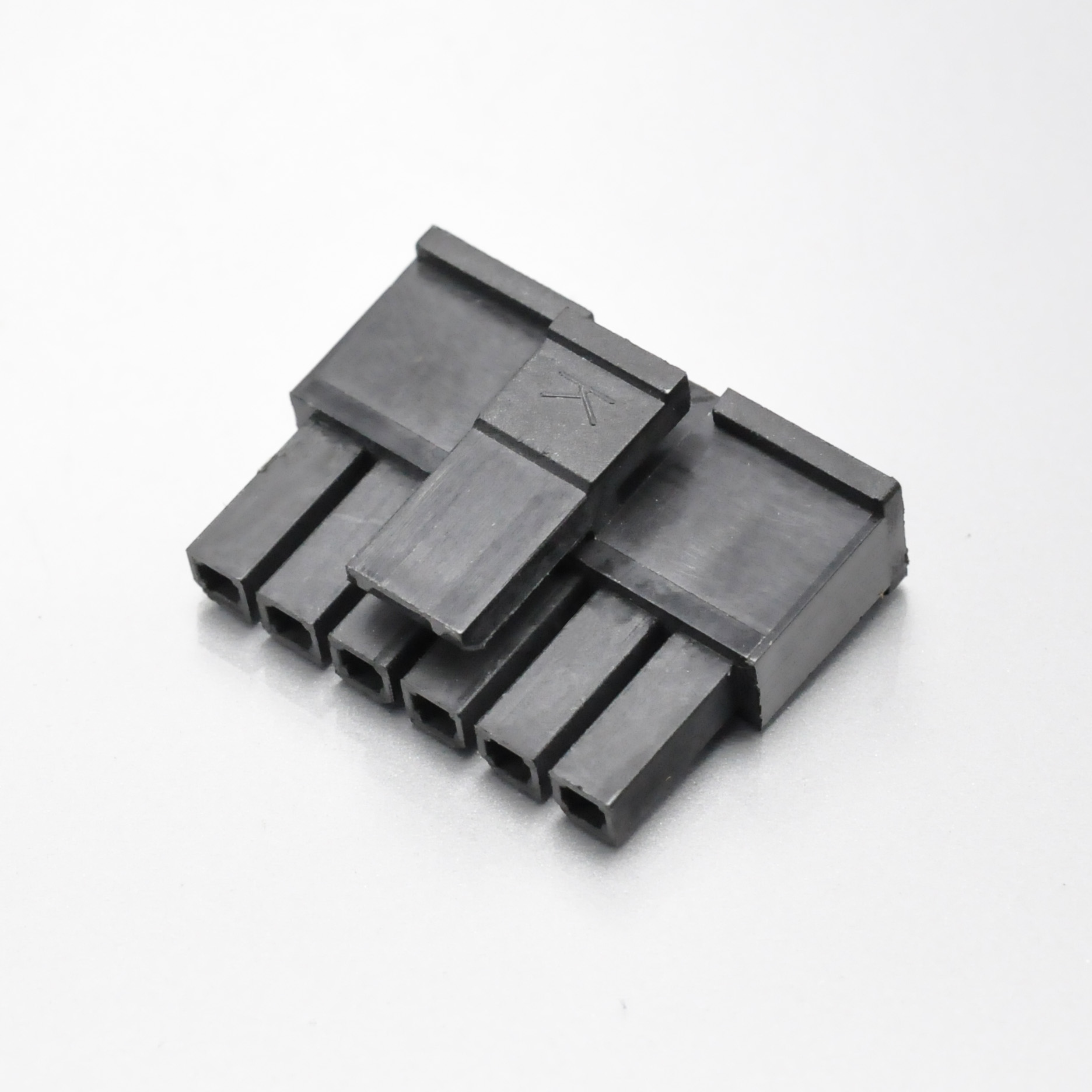
KONNRA KR3000 series single row male housing for the Molex Micro-Fit 3.0 pattern
The ratings side by side
Both manufacturers publish at more than one level, and the levels do not always agree with each other.
Figure Molex family datasheet Molex product specification KONNRA spec §4.0 KONNRA product page Pitch 3.00mm 3.00mm 3.00mm 3.00mm (wire-to-wire page shows 2.0mm in its at-a-glance table) Rated voltage 600V maximum 600V agency rating (UL, CSA and IEC) 250V 250V Rated current Up to 10.5A 5A, 7A or 8A single circuit, depending on the series and the agency 5A (20AWG) 5A Contact resistance 10 milliohms 10mΩ maximum, initial 10mΩ maximum 10mΩ (product landing page shows 20mΩ) Insulation resistance 1,000MΩ minimum 1,000MΩ minimum at 500VDC 1,000MΩ minimum at 500VDC 1,000MΩ (product landing page shows 100MΩ) Dielectric withstanding voltage Leakage <5mA two times the rated voltage plus 1,000 volts, VAC, 1 minute 1,500V AC, 1 minute 1,500V (product landing page shows 500V) Operating temperature Gold glow-wire −40 to +125°C; tin −40 to +105°C −40°C minimum; maximum 125°C gold / 105°C tin, by housing type −40 to +105°C −40 to +105°C, except two component pages Applicable wire 18–30 AWG 18–30 AWG (BMI: 20–30 AWG) 20# to 24# 20# to 24# Insulation diameter — 1.85mm max (18–24 AWG); 1.27mm max (26–30 AWG) 1.3 to 1.8mm 1.3 to 1.8mm (landing page shows 0.4 to 0.8mm) Durability Typically 30 cycles 30 mating cycles, tin or gold 30 cycles 30 cycles Mating force 8N maximum per circuit Per circuit, see the mechanical section 0.80kgf per circuit maximum not published Unmating force 2.4N minimum per circuit Per circuit, see the mechanical section 0.25kgf per circuit minimum not published Contact insertion force 14.7N maximum per contact 14.7N maximum 1.5kgf (14.7N) maximum not published Contact retention to housing 24.5N minimum 24.5N minimum 2.5kgf (24.5N) minimum not published Safety agency UL E29179 · CSA LR19980 UL E29179 · CSA LR19980 · IEC 61984 UL E482542 UL E482542 Housing material Nylon See the sales drawing PA66 UL94 V-0 or V-2 PA66, PA9T, PA46 or LCP Header material LCP See the sales drawing LCP (SMT) or PA9T / PA46 / LCP (DIP) Nylon 9T, PA46 or LCP Contact material Phosphor bronze, copper alloy See the sales drawing Phosphor bronze terminals; brass wafer pins Phosphor bronze, brass Plating 0.25µm select tin; 0.38µm and 0.76µm select gold Tin or gold, thickness by part number Tin or gold over nickel, thickness not published Tin over nickel; gold flash Three force pairs, and two of them are the original’s own numbers
Four force measurements exist in these documents and they do not share a basis: per contact, per circuit, whole-connector, and measured-on-a-gage-pin. Set them apart and the picture is unusually clean.
Force Molex published KONNRA published Basis Verdict Contact insertion force 14.7N maximum per contact 1.5kgf = 14.7N maximum One contact, into the housing Identical Contact retention to housing 24.5N minimum 2.5kgf = 24.5N minimum One contact, pull-out from the housing Identical Mating force 8N maximum per circuit 0.80kgf = 7.85N per circuit maximum Whole connector, divided by circuits Ours is 0.15N tighter Unmating force 2.4N minimum per circuit 0.25kgf = 2.45N per circuit minimum Whole connector, divided by circuits Ours is 0.05N stronger Pin retention in header 13.3N minimum (BMI spec), 13.7N minimum (dual-row spec) 1.5kgf = 14.7N minimum One header pin, axial push-out Ours is 1.0–1.4N stronger Wire pull-out / crimp strength 20 AWG 57.9N, 22 AWG 35.5N, 24 AWG 26.6N minimum (BMI spec); 20 AWG 57.8N, 22 AWG 35.6N, 24 AWG 22.2N minimum (test summary) 6.8 / 4.54 / 3.63kgf minimum = 66.7 / 44.5 / 35.6N at 20 / 22 / 24 AWG Crimped wire, axial pull Ours is higher at all three gauges The first two rows are the strongest claim in this guide, and they are checkable in one arithmetic step. Our specification writes the figures as 1.5 kgf (14.7 N) and 2.5 kgf (24.5 N) — and 1.5 × 9.80665 = 14.710N, 2.5 × 9.80665 = 24.517N. Our documents state both units, the conversion is exact, and the newton figures are the original’s newton figures. These are not two engineers arriving independently at a similar number; they are the same number.
The third and fourth rows are where it gets interesting, because the original’s two figures are a window and ours sit inside it. Molex publishes a maximum insertion force and a minimum withdrawal force — a corridor that converts to 0.8158kgf maximum and 0.2447kgf minimum per circuit; we publish 0.80kgf maximum and 0.25kgf minimum, a grid of two decimal places. Both conversions land on the stricter side: our maximum is lower than the original’s by 0.0158kgf, our minimum higher by 0.0053kgf. I cannot prove from the documents why the table was built that way, and I am not going to claim I can. What I can say is that the arithmetic is reproducible, the direction is safe in both cases, and the practical meaning is simple: the connector we ship is specified to take less force to mate and to hold on harder than the original requires.
Both columns bracket the original at every circuit count, not just on average. One thing the ladder does not show: our withdrawal minimum is identical at initial mate and at the 30th cycle, 0.25kgf per circuit in both columns, which models no withdrawal-force loss across the full rated life against our own §7.1 requirement that contact resistance stay at or below 20mΩ after the same 30 cycles. The original publishes no force-versus-cycle table, so do not read “0.25kgf at cycle 30” as a measured value. On crimp strength, our minimum at 20, 22 and 24 AWG is 66.7N, 44.5N and 35.6N against the original’s 57.9N, 35.5N and 26.6N in the BMI specification — our guaranteed 35.6N at 24 AWG is numerically the same as the original’s guaranteed minimum at 22 AWG, 35.5N. Two caveats: the original publishes two different minimums for 24 AWG (26.6N in the BMI specification, 22.2N in the test summary), and our method is stated as “Crimp strength” with no test rate cited, while Molex specifies wire pull-out at “25 ± 6 mm (1 ± ¼ inch) per minute.” Comparable in kind, not proven comparable in method.
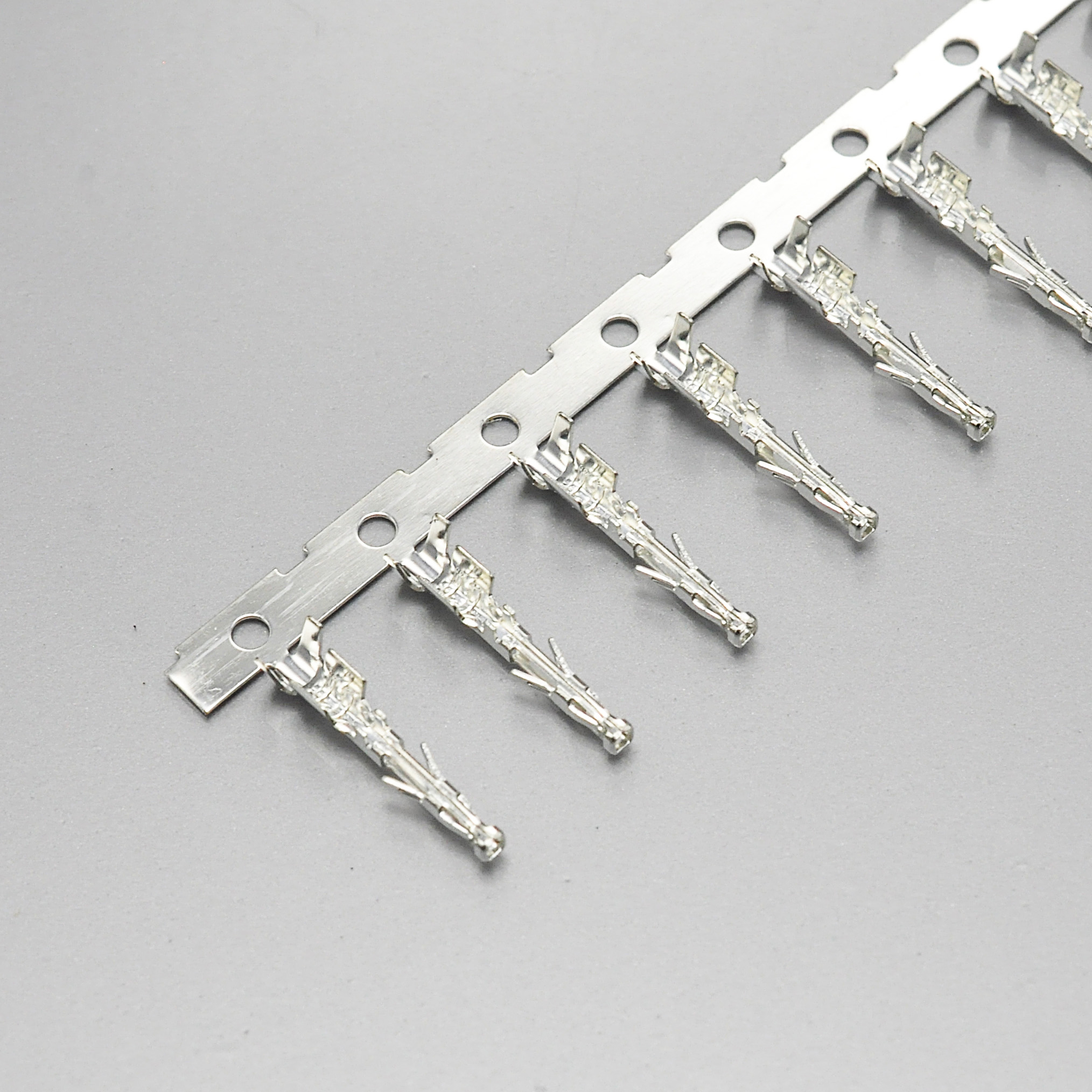
KONNRA KR3000 series female crimp terminal for the Molex Micro-Fit 3.0 pattern
The electrical sheet: five exact matches and three departures
Item Molex requirement KONNRA requirement Verdict Contact resistance, initial 10mΩ maximum (20mV, 100mA, dry circuit, wire resistance excluded) 10mΩ maximum (20mV, 100mA, EIA-364-23C) Match Insulation resistance 1,000MΩ minimum at 500VDC 1,000MΩ minimum at 500VDC, adjacent contacts, 1 minute Match, including the test voltage Durability 30 mating cycles, tin or gold 30 cycles at 10 cycles per minute Match Humidity 96 hours at 40 ± 2°C, 90–95% R.H. 96 hours at 40 ± 2°C, 90–95% R.H. Match Temperature-rise basis Derating table based on “not exceeding 30°C temperature rise” Temperature rise 30°C maximum Match The insulation-resistance row is the one to look at twice, because matching the value is easy and matching the test voltage is not. Both documents specify 500VDC applied for one minute between adjacent contacts and 1,000MΩ minimum; a supplier can pass a 1,000MΩ specification at a lower test voltage and the datasheet looks identical. Here it does not.
Item Molex KONNRA Direction Voltage rating 600V, UL, CSA and IEC agency rating 250V Original is 350V higher Insulation resistance after humidity 1,000MΩ minimum 100MΩ minimum Ours is one order of magnitude lower Salt spray 48 hours at 35 ± 2°C, 5% solution 24 hours at 35 ± 2°C, 5 ± 1% solution Ours is half the duration The voltage row is the single most consequential difference in this guide. Molex’s agency rating is 600V across UL, CSA and IEC, and the datasheet also quotes 600V maximum at product level. We publish 250V. A harness that is fine on a 400V DC bus with the original is not covered by our published rating, whatever else matches.
On the dielectric withstanding voltage the original publishes a formula rather than a number: apply “{two times the rated voltage plus 1000 volts} VAC for 1 minute between adjacent terminals and between terminals to ground.” At Molex’s own 600V that calls for 2,200VAC; our §5.3 states 1,500V AC for 1 minute, precisely what the same formula yields at 250V (2 × 250 + 1,000 = 1,500). The gap on this row is the rating, not the test method. The post-humidity insulation resistance is the row where we are weakest: our §7.7 requires 100MΩ minimum after humidity against the original’s 1,000MΩ — an order of magnitude. The same clause value appears in our 2.5mm, 2.54mm and 3.00mm specifications, so it reads as a family-template figure rather than a tested result for this series.
The wire window: three of the original’s seven rated sizes
Molex accepts 18 to 30 AWG stranded copper. We document 20# to 24#.
AWG Molex derating table, 2-circuit W-B Molex derating table, 24-circuit W-B KONNRA coverage 18 AWG 8.5A 5.0A not covered 20 AWG 7.0A 4.5A covered 22 AWG 6.0A 3.5A covered 24 AWG 5.5A 3.0A covered 26 AWG 4.5A 2.5A not covered 28 AWG 4.0A 2.0A not covered 30 AWG 3.5A 1.0A not covered Five nominal AWG steps out of thirteen, and three rows out of seven in the original’s own table. Four of the misses are fine gauges we simply do not document, a coverage statement rather than a defect for most power applications. The one that matters commercially is 18 AWG, because that is where the original’s headroom lives: 8.5A in a 2-circuit wire-to-board configuration, against our published 5A at 20 AWG. A customer using 18 AWG for a 6A load on a two-way connector is outside our documented window, and per Molex’s own table the original covers it. That single row is the first thing to check before quoting a cross-reference.
Read the table with the original’s own caveat attached: the values are “for REFERENCE ONLY”, based on “not exceeding 30°C Temperature Rise”, for “all circuits powered”, and “PCB trace design can greatly affect temperature rise results in Wire-to-Board applications.” Our single 5A figure is a rating, not a derating table. One comparison is genuinely favourable: Molex’s test summary measures 20 AWG at 5.5A and 24 AWG at 4.0A at 30°C maximum rise, while we publish 5A at 20 AWG — so at the coarsest gauge in our window we rate the part slightly below what the original measured for the same conductor.
And the insulation window is narrower at both ends
Wire Molex KONNRA 18–24 AWG 1.85mm maximum — 26–30 AWG 1.27mm maximum — 20–24 AWG 1.85mm maximum 1.3 to 1.8mm The original publishes a ceiling. We publish a corridor. Both of our ends exclude wires the original accepts.
- At the top end we are 0.05mm tighter. A 24 AWG wire with 1.83mm insulation is inside the original’s published maximum and outside ours.
- At the bottom end we impose a floor the original does not impose at all. A thin-wall 22 AWG wire with 1.2mm insulation is covered by the original’s document and rejected by ours.
A 0.05mm difference at the top is small enough to be invisible at the quotation stage and large enough to stop a crimp from closing. The floor is the bigger risk: no Molex Micro-Fit document states a minimum insulation diameter, so a designer who has validated one with thin-wall wire has no reason to look for a lower bound. If your wire is a thin-wall or dual-wall type, send the insulation diameter before you specify.
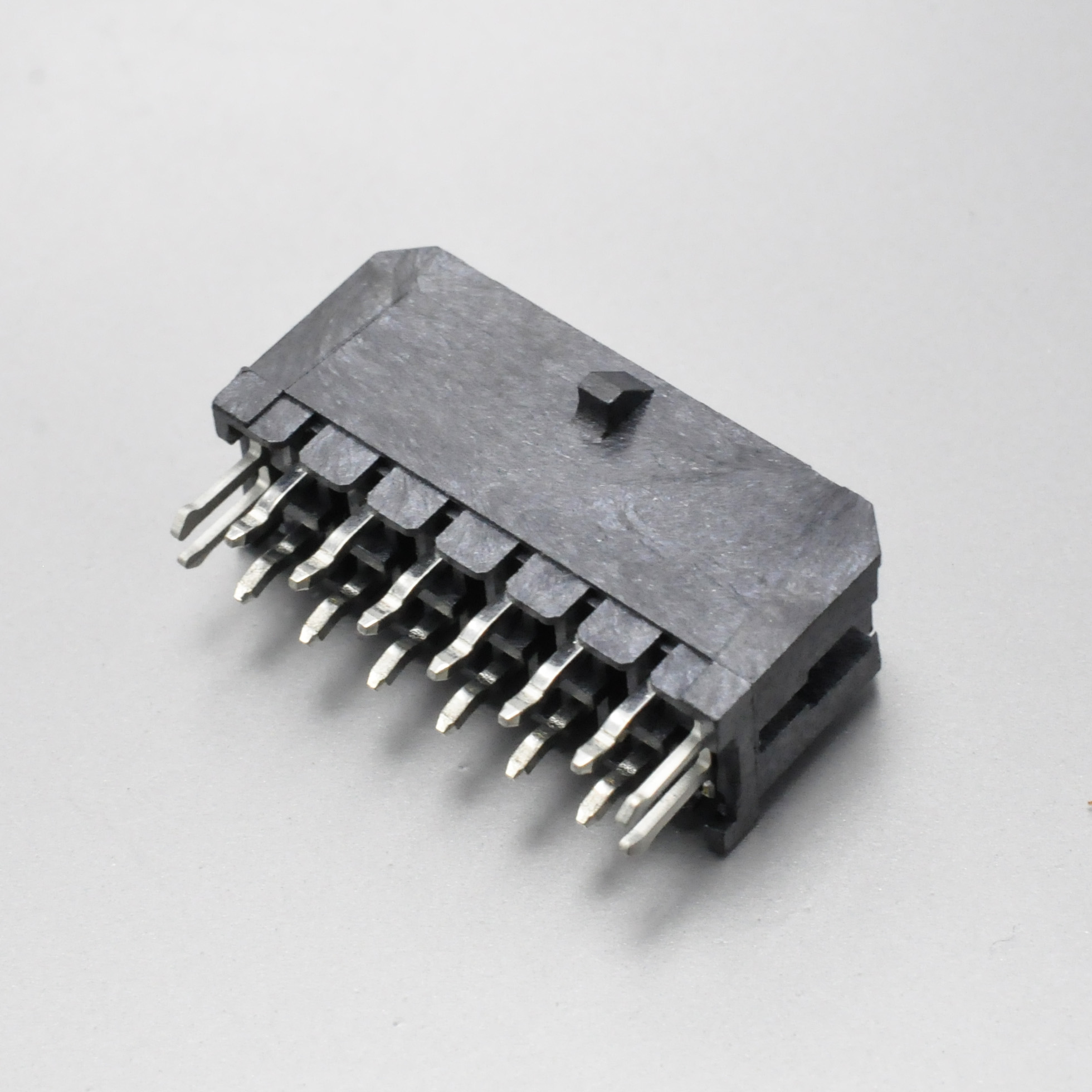
KONNRA KR3000 series DIP dual row straight wafer, vertical 3.00mm header
Materials: nylon and LCP on one side, three resins and a V-2 grade on the other
Molex’s family datasheet states the physical set in four lines: “Housing: Nylon. Header: LCP. Contact: Various (Phosphor Bronze, Copper Alloy — see product specifications for exact connector system).” Plating is published to the micron: 0.25µm select tin, or 0.38µm and 0.76µm select gold.
Component Molex KONNRA Male housing Nylon PA66, UL94 V-0 or V-2 Wire-to-wire female housing Nylon Nylon66, UL94 V-2 SMT wafer base LCP LCP, UL94 V-0 DIP wafer base LCP PA9T, PA46 or LCP, all UL94 V-0 Terminal Phosphor bronze / copper alloy Phosphor bronze Wafer contact pin Phosphor bronze / copper alloy Brass, matte tin or tin/gold over nickel Plating thickness 0.25µm tin; 0.38µm / 0.76µm gold not published Our DIP wafers are documented in three different resins across different part numbers: the specification lists the DIP base as “PA9T or PA46 or LCP UL94 V-0”, and the component pages resolve to Nylon 9T (PA9T) on the DIP single-row right-angle wafer page, PA46 on the DIP dual-row straight wafer page and LCP on the SMT dual-row right-angle wafer page. The original’s header material is one answer — LCP — and ours is three answers by part number. If you are matching a reflow profile, ask for the resin on the exact part number.
One housing grade on our side is UL94 V-2, not V-0: the wire-to-wire double-row female housing is published as
Nylon66 UL94 V-2on our own engineering drawing, while Molex’s standard Micro-Fit housings are UL 94V-0, with 94V-2 available only as an option on the TPA dual-row receptacle172952. And we publish no plating thickness anywhere — Molex’s call-outs are what a durability calculation is built on, and thicker gold is how the original reaches 1,000 hours of thermal ageing at 125°C with gold-plated terminals against 240 hours at 105°C with tin. Where our documentation does something better: our wire-to-wire specification marks the entire wafer block N/A — §2.0 lists the wafer as “None” and §3.0 records “N/A” for the SMT base, contact and solder tab, and again for DIP, because a wire-to-wire connector has no header.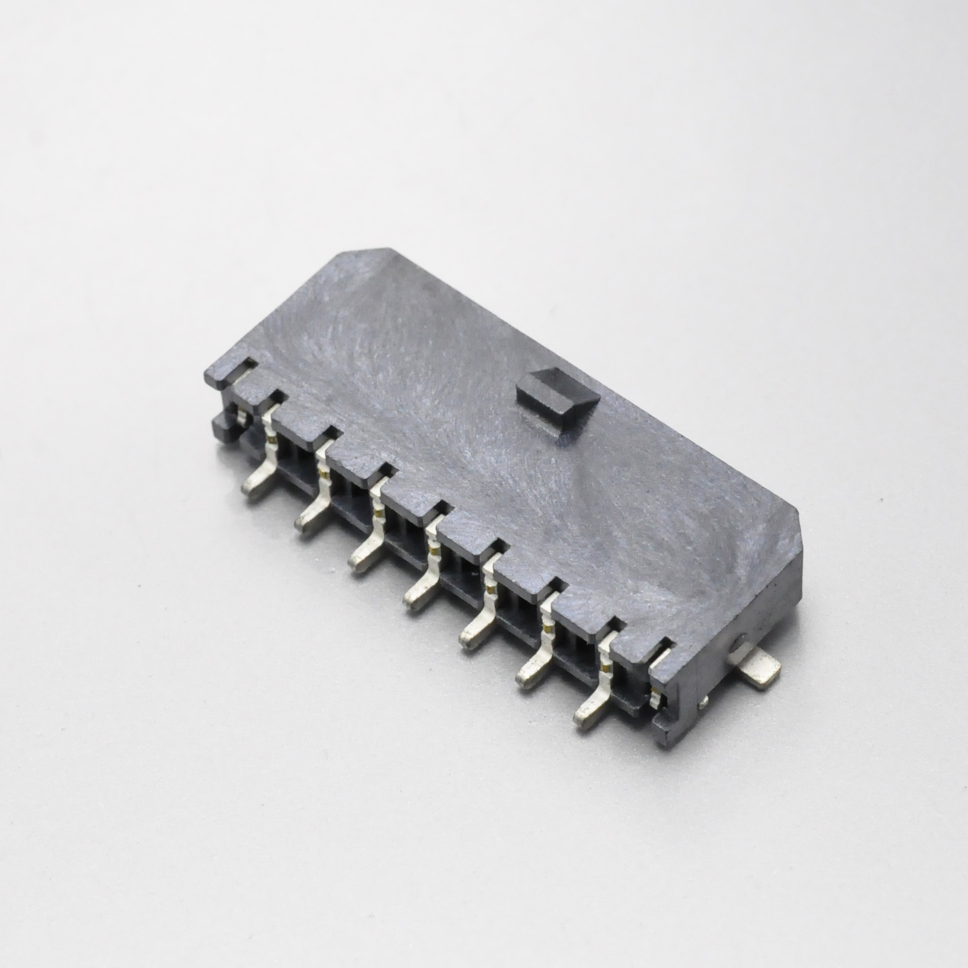
KONNRA KR3000 series SMT single row right angle wafer with solder tab, 3.00mm reflow header
What the original publishes that we do not
A cross-reference guide that lists only what the two parts share is a sales document. This section is the engineering one.
- Plating thickness and agency coverage. Molex publishes 0.25µm select tin and 0.38µm / 0.76µm select gold over nickel, carries UL file E29179 and CSA file LR19980, and states compliance with IEC 61984 with an “NRTL type examination certificate available from Molex upon request”. We publish UL E482542 only, and no plating thickness.
- Contact wipe, capacitance and normal force. Molex publishes the nominal wipe for each mating combination — 2.11mm, 1.75mm, 1.72mm and 1.60mm — plus capacitance of 2 picofarads maximum at 1 MHz and a normal force of 2.7N (0.6 lbf) minimum, measured at 331g mean. We publish none of the three.- The FMLB and RMF terminal options. Molex offers a hot-mating FMLB terminal (
43031-1***) and a reduced-mating-force terminal (46235,203951). Our series publishes two female terminals,T3000FP***01AandT3000FP***01C, and does not state what distinguishes them.
Where our own documents disagree with each other
A cross-reference is only as good as the weaker of the two catalogues.
1. The wire-to-board landing page publishes four electrical values that belong to a different product.
Field Landing page publishes Our own specification says Two sibling pages say Insulation O.D 0.4 to 0.8mm 1.3 to 1.8mm 1.30–1.80mm Withstanding voltage 500V AC / minute 1,500V AC 1 minute 1,500V AC Contact resistance 20mΩ max 10mΩ max 10mΩ max Insulation resistance 100MΩ min 1,000MΩ min 1,000MΩ min All four appear on the other two KR3000 product pages with the correct figures. The insulation row is urgent, because 0.4 to 0.8mm is narrower than a real 20–24 AWG wire’s insulation — wrong in the direction that would make a designer reject a wire that actually fits.
2. The wire-to-wire page states a 2.0mm pitch in its specification block, while its own title, image filenames and body text say 3.00mm. 3. It also contradicts itself on temperature, promising “up to 125°C” above a table that says −40 to +105°C — the 125°C figure is the original’s gold ceiling, not ours. 4. Two component pages still carry −25°C to +85°C — the male terminal and the single-row female housing with wings — against −40 to +105°C everywhere else. 5. The male terminal page publishes AWG 28#–22# with insulation 1.80mm (Max), against our specification’s 20# to 24# and 1.3 to 1.8mm.
6. The “Compatible” field carries two different meanings inside one family, and one of them must be wrong. The terminal and wafer pages only make sense if the field means “replaces”; the three housing pages only make sense if it means “mates with”. Both readings cannot be right, and in Molex naming the receptacle holds the female crimp terminals while the plug holds the male ones.
7. Our wire-to-board crimp table is titled “(Male Terminal)” while its own part list contains no male terminal. Section §6.5 of PS-KR3000-01 gives crimp data for 20, 22 and 24 AWG, but §2.0 lists
T3000FP***01AandT3000FP***01C, both female. Either a male terminal is missing from the part list, or the heading is a template leftover.8. The KR3000 wiring harness page is empty — a hero image, an enquiry form and a category list, and its component selector returns “No results found.” 10. Component pages use two different prefixes for the same series (
mx3-0-vd-dual,mx3-0-rs-dual,mx3-0-rd-single-wfalongsidekr3000-single-row-m-hsgand others). 11. One existing page is out of step with this review: an article on the same site describes a “high-temperature UL 94V-0 liquid crystal polymer” housing, calls the part “glow wire compatible” and states a “2 to 24 circuits” range, while our specification says PA66 UL94 V-0 or V-2, we publish no glow-wire data, and the wire-to-board range is 2 to 12 single row and 2×1 to 2×12 dual row. A KR3000 landing page is also titled with “Mini-Fit 3.0” — Molex’s 4.2mm family, an entirely different pitch.
KONNRA KR3000 series single row female housing for the Molex Micro-Fit 3.0 pattern
The cross-reference map
KONNRA component Molex series KONNRA part number pattern Positions Single-row male housing 43640(single-row plug)H3000M1****01A2 to 12 Dual-row male housing 43020(dual-row plug)H3000M2****01A2×1 to 2×12 Single-row female housing 43645(single-row receptacle)H3000F1**04**B2 to 12 Dual-row female housing 43025(dual-row receptacle)H3000F2**04**B2×1 to 2×12 Female crimp terminal 43030,46235T3000FP***01A,T3000FP***01C— Male crimp terminal 43031T3000MP***01B— SMT right-angle wafer, single row 43650(single-row header)C3000RS1*****2 to 12 SMT right-angle wafer, dual row 43045(dual-row header)C3000RS2*****2×1 to 2×12 SMT straight wafer, single row 43650C3000VS1*****2 to 12 SMT straight wafer, dual row 43045C3000VS2*****2×1 to 2×12 DIP right-angle wafer, single row 43650C3000RD1*****2 to 12 DIP right-angle wafer, dual row 43045C3000RD2*****2×1 to 2×12 DIP straight wafer, single row 43650C3000VD1*****2 to 12 DIP straight wafer, dual row 43045C3000VD2*****2×1 to 2×12 TPA 171850,172952,200875,203632,172953none published — Blind-mate floating set 44133,44300,44428,44432,44764,44769,45280none published — Compliant-pin header 44914none published — Every Molex series in that table is a real Micro-Fit 3.0 series, and the last three rows are coverage gaps rather than identification errors. Our wafer ordering codes are compound — family, orientation, row count, circuit count, a type code, a variant letter and a plating code — and cannot be decoded from the product specification alone.
Applications where the Micro-Fit pattern is used
Market Applications as published by Molex Appliance Freezers, HVAC systems, printers, refrigerators, scanners, security systems, smart homes, washing machines Automotive Harness manufacturers, interior automotive devices, non-sealed applications Industrial Routers and switches, servers, storage systems Power for data centre Routers and switches, servers, storage systems Telecommunications Routers and switches, servers, storage systems Sourcing: what procurement teams ask
- Which half of the pair am I buying? The most common error with a 3.00mm crimp system, and the “Compatible” field on three of our housing pages currently names the opposite gender. Quote the part number, not the compatibility field.
- Can you hold the specification? Reference the part number and the specification revision — PS-KR3000-01 revision A1 for wire-to-board and PS-KR3000-02 revision A1 for wire-to-wire. Our specifications state plainly: “Any change or revision for the product specification will not be announced in advance.”What is the minimum order quantity and lead time? Connector production lead time is typically 2 to 4 weeks and wiring harness lead time typically 3 to 4 weeks, with complete connector set samples within 45 days.
The five questions I would ask us, in this order
1. “My circuit is 400V DC. Is the KR3000 rated for it?” No. Our published rating is 250V; the original’s agency rating is 600V. A 250V rating on a 400V bus is not a documentation gap, it is outside the specification.
2. “I use 18 AWG at 6A on two circuits. Does the KR3000 cover it?” No. Our documented range is 20# to 24#, while the original’s table rates 18 AWG at 8.5A in a 2-circuit wire-to-board configuration. A coverage limit, not a quality difference.
3. “My wire has 1.2mm insulation. Will it crimp?” Not to our published window, which starts at 1.3mm — and the original publishes no lower bound at all. Ask as a diameter, not as a gauge.
4. “What does the second female terminal do that the first one does not?” We publish
T3000FP***01AandT3000FP***01Cwith no statement of the difference, while the original documents its second female terminal explicitly as the reduced mating force version. If insertion force matters in your assembly, this is the highest-value question on the list.5. “What is the retention force after 30 cycles, measured rather than specified?” Our §8.0 gives 0.25kgf per circuit at both initial and cycle 30, which models no loss over life. Ask for the measured ladder.
Engineer’s pre-release checklist
- Voltage. Confirm the working voltage against 250V, not the original’s 600V.
- Current at your gauge. Our rating is 5A at 20 AWG; above that, or at 22/24 AWG, ask for the derating answer in writing.
- Wire. Check the gauge (20#–24#) and the insulation diameter (1.3–1.8mm) separately — a wire can pass one and fail the other.
- Housing grade. Confirm UL94 V-0 on the specific housing; our wire-to-wire double-row female housing is published as V-2.
- Wafer resin. Our DIP wafers appear as PA9T, PA46 or LCP by part number; the original’s header is LCP.
- Solder profile. Our SMT peak is 255 ± 5°C against 260 +0/−5°C, and we publish no ramp rate and no time-to-peak.
- Vibration and shock. Ours is a swept sine to EIA-364-28B; the original’s is random vibration at condition VII.
- Environmental life. Heat ageing is 96 hours at 105°C against 240, salt spray 24 hours against 48, and post-humidity insulation resistance 100MΩ against 1,000MΩ.
- Retention. Confirm the terminal-to-housing minimum of 2.5kgf (24.5N) and ask for the measured pull-out ladder.
Frequently asked questions
So what is a Molex Micro-Fit 3.0 connector?
Molex’s 3.00mm (.118 inch) pitch crimp family for wire-to-board and wire-to-wire power and signal connections, built on a positive friction lock with an optional terminal position assurance device. It is documented across separate single-row and dual-row specifications, with female crimp terminals in
43030and46235, male terminals in43031, housings in43020,43025,43640and43645, and headers in43045,43650,44067and44914, rated at 600V and up to 10.5A over 2 to 24 circuits.Is Micro-Fit the same as Mini-Fit?
No. Micro-Fit is 3.00mm pitch; Mini-Fit is 4.2mm pitch — different families, terminals and current ratings, not interchangeable. Our own site has a KR3000 page titled “Mini-Fit 3.0”.
What is the KONNRA equivalent of the Molex Micro-Fit 3.0?
The KR3000 series — a 3.00mm pitch crimp family covering wire-to-board and wire-to-wire in 2 to 12 circuits single row and 2×1 to 2×12 dual row, with PA66 housings, LCP/PA9T/PA46 wafers, phosphor bronze terminals and brass wafer pins, rated 250V, 5A at 20 AWG, −40 to +105°C, 10mΩ contact resistance and 1,000MΩ insulation resistance at 500VDC.
What voltage and current does each carry?
Molex rates the family at 600V, with agency single-circuit ratings of 8A on the receptacles and headers and 5A on the plug housings, plus a headline “up to 10.5A”. Ours is 250V and 5A at 20 AWG. Molex’s test summary measures 20 AWG at 5.5A and 24 AWG at 4.0A at 30°C maximum rise, so our figure is conservative at the gauge it names — but it is a rating, not a derating table.
What are the contact resistance and insulation resistance?
10 milliohms maximum, initial, at 20mV and 100mA with wire resistance excluded, and 1,000 megohms minimum at 500VDC for one minute between adjacent contacts. The KR3000 publishes the same two figures with the same test conditions. Molex’s own test summary reports 19.95mΩ for wire-to-wire, of which roughly 16.6mΩ is the bulk resistance of 13 inches of test wire.
What wire gauge and insulation diameter does each accept?
Molex: 18 to 30 AWG stranded copper, with a maximum outside insulation diameter of 1.85mm for 18–24 AWG and 1.27mm for 26–30 AWG, and no minimum. The KR3000 documents 20# to 24# and a corridor of 1.3 to 1.8mm. The gap that matters commercially is 18 AWG, which Molex rates at up to 8.5A in a 2-circuit wire-to-board configuration.
What are the mating and unmating forces?
Molex publishes 8N maximum insertion and 2.4N minimum withdrawal per circuit; our ladder is 0.80kgf (7.85N) and 0.25kgf (2.45N) — inside the original’s window at both ends. At contact level Molex publishes 14.7N maximum insertion and 24.5N minimum retention, and we publish 1.5kgf (14.7N) and 2.5kgf (24.5N) — the same two numbers.
Does the KR3000 have a TPA or a blind-mate version?
No. Molex documents a full TPA system —
171850and200875in 2 to 7 circuits,172952in 4 to 22 circuits, a retainer172953, two TPA parts per receptacle — and a blind-mate floating system with a 2.54mm misalignment allowance and a recommended maximum mating speed of 40 mm/sec. Our wire-to-board page says the series is “still suitable for blind mating applications” without publishing an allowable misalignment.What are the housing and wafer materials?
Molex states Housing: Nylon, Header: LCP, Contact: various phosphor bronze and copper alloy, plated at 0.25µm select tin or 0.38µm / 0.76µm select gold over nickel. Our housings are PA66 in UL94 V-0 or V-2 — Nylon66 UL94 V-2 on the wire-to-wire double-row female housing — our SMT wafer base is LCP and our DIP wafer base is PA9T, PA46 or LCP by part number, with phosphor bronze terminals, brass wafer pins and plating of unpublished thickness.
What environmental tests does the Micro-Fit 3.0 require?
Thermal ageing for 240 hours at 105 ± 2°C with tin or 1,000 hours at 125 ± 2°C with gold; humidity at 40 ± 2°C and 90–95% R.H. for 96 hours; cold resistance at −40 ± 3°C for 96 hours; thermal cycling to 500 cycles between 15 and 85°C; salt spray for 48 hours; random vibration to EIA-364-28 condition VII; mechanical shock at 50 g half-sine for 11 ms, 18 shocks; and flowing mixed gas to EIA-364-65 class 2A. Contact resistance may change by no more than 20mΩ from initial. The KR3000 runs 96 hours of heat ageing, 96 hours of humidity, 5 thermal-shock cycles, 24 hours of salt spray and a swept-sine vibration to EIA-364-28B, with matching cold resistance at 96 hours and −40°C.
What UL and CSA files does the Micro-Fit 3.0 carry?
UL file E29179 and CSA file LR19980, plus IEC 61984 certification with an NRTL type examination certificate available on request. The KR3000 component pages publish UL file E482542 only — if your approval file references a CSA registration, that is a gap to close before you can list the part.
Is the KR3000 a drop-in replacement for the Micro-Fit 3.0?
On fit, retention and the interface the case is strong — 3.00mm pitch, the same position ranges, matching contact and insulation resistance including the test voltage, matching 30-cycle durability and humidity duration, and contact insertion and retention forces published as the same numbers. On three points the answer is no: 250V against 600V, 20#–24# against 18–30 AWG, and 100MΩ post-humidity against 1,000MΩ. Treat it as a drop-in for a ≤250V, ≤5A, 20–24 AWG application and as an evaluated alternative anywhere else.
Start your cross-reference check
KONNRA supplies the KR3000 series as individual components, crimped housing assemblies or complete cable assemblies, with customisation available for application-specific requirements.
- Request a quote — pricing, MOQ and configuration for your circuit count and wire
- Request the voltage statement in writing — for any working voltage above 250V AC/DC
Contact KONNRA Electronics — Phone (86)-769-85449875 · Email info@konnra.com · No.6 Nanchang South Road, Chijiao, Wangniudun, Dongguan, Guangdong, China · Contact us · KR3000 Series Wire-to-Board product page · KR3000 Series Wire-to-Wire product page
Sources and method. Every figure here is taken from a manufacturer document, and where two manufacturers — or two documents from the same manufacturer — disagree, the difference is stated rather than averaged. Molex figures come from the Micro-Fit Connectors family datasheet (987650-5984); PS-43045 revision P4 (2021/06/03, 21 sheets — Micro-Fit 3.0 dual-row connectors); PS-43650 revision N2 (2020/08/10, 20 sheets — Micro-Fit 3.0 single-row connectors); PS-44300-001 revision L3 (2016/02/17, 12 sheets — Micro-Fit BMI floating connector system); and TS-43045-001 revision A3 (2020/01/06, 10 sheets — Micro-Fit 3.0 test summary). KONNRA figures come from PS-KR3000-01 revision A1 (2022/2/26, 8 pages — 3.00mm pitch KR3000 series wire-to-board connector specification) and PS-KR3000-02 revision A1 (2022/2/26, 7 pages — wire-to-wire connector specification), the three KR3000 product pages, the KR3000 wiring harness page, the twelve KR3000 component pages, and the KR3000 wire-to-board and wire-to-wire engineering drawings (including the male housing drawing REV A6, the female housing drawing, the female terminal drawing REV A5, and the wafer drawings REV A3). The current product specifications are dated 2022/2/26 and carry edition A1, while the drawings have been revised since. Every force comparison is stated with its basis: per-contact, per-circuit and whole-connector figures are not interchangeable, and the original’s two per-circuit figures are a maximum and a minimum.
https://konnra.com/molex-micro-fit-3-0-connector-complete-guide/
Dongguan Konnra Electronics Co., Ltd -
AuthorPosts

- You must be logged in to reply to this topic.