

- This topic is empty.
-
AuthorPosts
-
2026-09-14 at 2:49 pm #11418
Quick answer: The JST SUR 0.8 connector is a 0.8mm pitch, single-row, wire-to-board insulation displacement (IDC) connector with SMT mounting and a friction lock. It is rated 0.5A AC/DC at 30V (0.2A with AWG #36 wire), accepts AWG #36, #34 and #32 wire with an insulation diameter of about 0.39mm, and is available in 2 to 22 circuits. The KONNRA KR0800 series is documented as its cross-reference equivalent.
The JST SUR holds a specific distinction in the connector world: it was the first 0.8mm pitch wire-to-board insulation displacement connector to reach the market. At that pitch, there is simply no room for a conventional crimp contact and a stripped wire — so the SUR approach is to press the unstripped wire directly into a slotted contact, removing stripping and crimping from the assembly process entirely.
That design choice is why the SUR sits at the extreme compact end of wire-to-board interconnects. A side-entry SUR measures only 1.75mm high and 3.9mm deep after board mounting, which takes roughly 34% less board area than a comparable 1.0mm pitch connector.
A note on naming: this part appears as JST SUR0.8 connector, JST SUR 0.8, SUR0.8, SUR 0.8mm, “JST SUR connector”, and “0.8mm JST connector” in listings and searches. They all refer to the same JST SUR series. This guide also cross-references the KONNRA KR0800 series, which KONNRA documents as the SUR 0.8 equivalent.
Key Specifications at a Glance
Attribute JST SUR 0.8 KONNRA KR0800 Pitch 0.8mm 0.8mm Termination Insulation displacement (IDC) Insulation displacement (IDC) Mounting SMT (side entry, top entry) SMT (straight 180°, right-angle 90°) Current rating 0.5A AC/DC (AWG #32); 0.2A AC/DC (AWG #36) 0.5A Voltage rating 30V AC/DC 30V Circuits 2, 3, 4, 5, 6, 8, 10, 12, 14, 15, 16, 20, 22 2 – 20 Wire size AWG #36, #34, #32 AWG #32 (series documentation) Insulation O.D. φ0.39mm See the note in the specification section Rows Single Single Lock Friction lock Locking features on the shrouded header Operating temperature −25°C to +85°C −40°C to +105°C Insulation resistance 100MΩ min. 100MΩ min. Withstanding voltage 200V AC for 1 minute 200V AC / minute Plating Gold Gold over nickel Standards CSA, UL UL product and operational safety certification Both columns are compiled from manufacturer product documentation, not from distributor listings. Sources are noted at the end of this guide.
What Is the JST SUR 0.8 Connector?
The JST SUR is a 0.8mm pitch, single-row, wire-to-board connector that terminates by insulation displacement rather than crimping. The PCB side is an SMT shrouded header; the wire side is an IDC housing into which the wire is pressed.
A complete connection needs just three parts:
- SMT wafer — the PCB-side shrouded header, in straight (top entry) or right-angle (side entry) form
- IDC housing — the wire-side body that presses the unstripped wire into the contact
- Cable assembly — optional pre-terminated harness built on the housing
There is no separate crimp terminal, because there is no crimp. That is the defining difference between this family and every crimp-style connector in the KONNRA JST-equivalent range.
Key characteristics:
- 0.8mm pitch, single row — 2 to 22 circuits depending on series
- IDC termination — no wire stripping, no crimping, no crimp tooling
- Ultra-fine wire — AWG #36, #34 and #32, with insulation around 0.39mm
- Low profile — 1.75mm mounted height for side entry; 3.9mm for top entry
- SMT only — there is no through-hole SUR
- Friction lock — with locking features on the shrouded header
- Gold plating over nickel for the contact system
- Vacuum-gripping friendly — the header shroud has no holes that would interfere with automated pick-and-place vacuum nozzles, which matters for high-volume SMT assembly
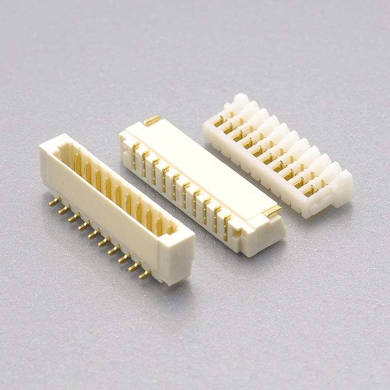
Figure 1 — KONNRA KR0800 series: 0.8mm pitch SUR IDC wire-to-board connector **View the KONNRA KR0800 SUR IDC Connector**
What Is an Insulation Displacement Connector (IDC)?
An insulation displacement connector makes its electrical joint by pushing an unstripped wire into a contact slot that is slightly narrower than the conductor. The slot cuts through the insulation and wipes against the copper, forming a gas-tight connection — in a single press, with no stripping and no crimping.
At 0.8mm pitch, this is not a convenience feature. It is the only practical way to terminate the wire involved.
Consideration IDC (JST SUR 0.8 / KR0800) Crimp at the same pitch Wire prep None — insert the wire as supplied Strip 1mm-class lengths without nicking a 0.2mm conductor Tooling A hand press or benchtop IDC tool Precision crimper with a die matched to the terminal Process risk Single press; position is set by the housing Strip length, crimp height, and wire placement all vary Suitability for AWG #36 Practical Impractical — conductor is too fine to crimp repeatably Field repair Re-termination needs a new housing Contact can be replaced individually Why this matters for your BOM and your build. With AWG #36 and #34 wire, a marginal crimp is invisible and intermittent, and it usually surfaces as a field failure rather than a line reject. IDC moves that variability into the moulded housing geometry, where it is fixed. In practice this means fewer process variables to control, less operator skill required, and a more consistent joint at high volume.
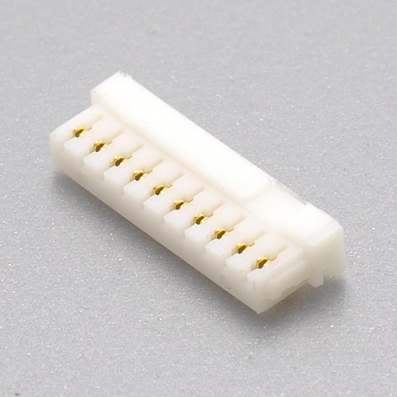
Figure 2 — KR0800 0.8mm pitch IDC housing, where the insulation displacement joint is made JST SUR 0.8 = KONNRA KR0800: Part Number Cross-Reference
JST SUR component JST part number pattern KONNRA equivalent Wire-side IDC housing NN SUR-GGS — e.g. 12SUR-32S (12 circuits, AWG #32), 06SUR-32S (6 circuits) KR0800 Housing PCB-side SMT shrouded header SUR SMT header, side entry and top entry KR0800 straight 180° / right-angle 90° wafer Compatible crimp-style alternative SUH connector, e.g. SUHR-02V-S-B (same footprint class, crimp termination) Not offered in KR0800 Reading the JST part number. JST encodes both the circuit count and the applicable wire size into the SUR part number — `12SUR-32S` is a 12-circuit part for AWG #32 wire. That makes the housing part number the fastest way to confirm what a cable assembly actually is, without measuring it.
Why JST offers a crimp alternative. JST documents a SUH crimp-style connector alongside the SUR, for users who need individual contact replacement or prefer crimp termination. The two are not substitutes for each other at the terminal level, so decide which termination method you are specifying before you build a BOM around a footprint.
Note on mounting style: both the JST SUR and the KONNRA KR0800 are SMT-only systems. If a design assumes a through-hole or DIP footprint for a 0.8mm pitch part, neither family will fit it.
JST SUR 0.8 / KONNRA KR0800 Specifications
Parameter JST SUR 0.8 (JST documentation) KONNRA KR0800 (KONNRA documentation) Pitch 0.8mm 0.8mm Row configuration Single row Single row Connection type Wire-to-Board Wire-to-Board Termination Insulation displacement (IDC) Insulation displacement (IDC) Current rating 0.5A AC/DC (AWG #32); 0.2A AC/DC (AWG #36) 0.5A Voltage rating 30V AC/DC 30V Circuits 2 – 22 (discrete counts) 2 – 20 Conductor size AWG #36, #34, #32 AWG #32 (per series documentation) Insulation O.D. φ0.39mm 0.8mm as listed in the general specification — confirm against the drawing Insulation resistance 100MΩ min. 100MΩ min. Withstanding voltage 200V AC for 1 minute 200V AC / minute Contact resistance — 20mΩ Max Operating temperature −25°C to +85°C −40°C to +105°C Plating Gold Gold over nickel Material — PA66 / LCP, UL94, phosphor bronze Mounting SMT: side entry, top entry SMT: straight 180°, right-angle 90° Lock Friction lock Locking features on the shrouded header Standards CSA, UL UL product and operational safety certification ” — ” indicates the parameter is not stated in the manufacturer documentation reviewed for this guide. Confirm any blank against the current JST SUR datasheet before releasing a drawing.
Specification differences worth verifying before you cross-reference
1\. Wire sizes. JST documents the SUR for AWG #36, #34 and #32, at 0.5A with AWG #32 and derated to 0.2A with AWG #36. KONNRA’s KR0800 series documentation references AWG #32. If your design uses #34 or #36 wire, confirm the accepted conductor range against the KR0800 product specification before you commit — finer wire changes both the current derating and the housing’s grip.
2\. Insulation diameter. JST specifies an insulation O.D. of φ0.39mm. KONNRA’s general specification table for the KR0800 lists 0.8mm, which equals the pitch and is most likely a data-entry carry-over rather than the accepted insulation range. Treat the drawing, not the summary table, as authoritative here, and confirm the accepted insulation diameter for your specific wire.
3\. Circuit count upper end. JST lists circuits up to 22 positions. KONNRA’s KR0800 product table documents 2–20 circuits, while KONNRA’s own series overview describes the family as covering 2P to 22P. If you need 21 or 22 positions, ask for confirmation rather than assuming.
4\. Operating temperature. JST documents the SUR at −25°C to +85°C. The KONNRA KR0800 is documented at −40°C to +105°C — a 15°C gain at the top end and a 15°C gain at the bottom. For equipment that sees outdoor use or thermal cycling, that difference is a qualification item, not a footnote.
5\. Contact resistance. KONNRA documents the KR0800 at 20mΩ max. JST’s published SUR summary does not state a contact resistance figure in the same place, so do not assume the two numbers are directly comparable — request the test data for both if this parameter is critical.

Figure 3 — KR0800 right-angle (90°) SMT wafer for side-entry mounting How Does the JST SUR 0.8 Compare to Other Compact Connectors?
Picking a connector for a tight board usually means choosing between four approaches. The table below places the SUR against the alternatives, with the KONNRA series for each.
Option Pitch Termination Mounting Typical current KONNRA series JST SUR 0.8 0.8mm IDC (no strip, no crimp) SMT, 1.75mm side-entry height 0.5A KR0800 JST SH 1.0 1.0mm Crimp, AWG #32–#28 SMT 1A KR1000 JST GH 1.25 1.25mm Crimp, AWG #30–#26 SMT 1A KR1259 JST ACH 1.2 1.2mm Crimp SMT 1A KR1201 FFC / FPC 0.5 – 1.0mm Board-mounted flex cable SMT 0.5 – 2A QZ000372 / QZ000373 How to choose between them. The SUR wins when the constraint is height and depth on the board, and when the wire is too fine to crimp reliably. The SH and GH win when you need more current per contact (1A versus 0.5A) and can afford a slightly larger footprint. FFC/FPC wins when the run is board-to-board rather than board-to-cable, and when you can tolerate the cable being permanently attached at both ends.
A practical caution. These families are not interchangeable, and pitch alone does not predict fit. A 0.8mm SUR wafer will not accept a 1.0mm SH housing, and an IDC housing cannot be re-terminated like a crimp contact. Cross-reference on the specific part number.
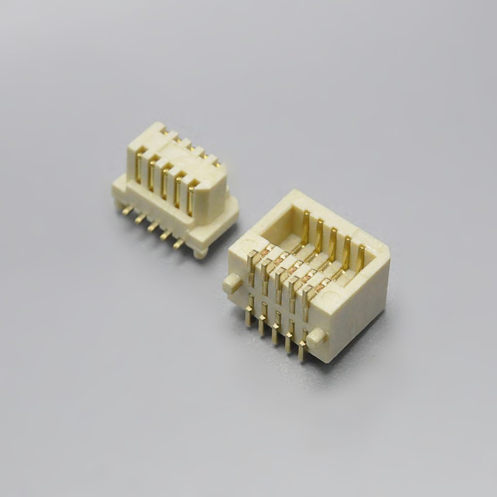
Figure 4 — KONNRA KR0802 0.8mm pitch board-to-board SMT connector, for board-to-board runs that do not need a cable Board Space: What 0.8mm Pitch Actually Buys You
Claims about “smaller connectors” are easy to make and hard to check. For the SUR, three published numbers make the trade-off concrete.
Measurement JST SUR side entry JST SUR top entry Mounted height above the board 1.75mm 3.9mm Depth into the board area 3.9mm 2.2mm Against a typical 1.0mm pitch connector, the side-entry SUR occupies roughly 34% less board area. The direction of the saving matters as much as the amount:
- Side entry (right-angle wafer) minimises height. Choose it when the board is stacked under a lid, inside a low enclosure, or beneath another PCB.
- Top entry (straight wafer) minimises depth. Choose it when the connector sits in the middle of the board and edge clearance is not available.
One detail that saves a production step. The SUR shrouded header has locking features for its mating housing but no holes in the shroud. Holes in a header shroud give vacuum from a pick-and-place nozzle somewhere to leak, which forces either a special nozzle or a taped part. With no holes, the header can be placed with the same vacuum nozzle as the rest of the SMT line. If you are quoting an automated assembly, that is worth confirming explicitly with your supplier.
Board design notes:
- Confirm straight 180° or right-angle 90° before quoting — the two need different pad geometry and different enclosure clearance.
- The wire side is IDC. Build your assembly instructions around a press operation, not a crimp operation, and specify the correct bench tool or press.
- Because accommodation is tight at 0.8mm pitch, an out-of-spec insulation diameter is a real failure mode. Tie the accepted wire OD to the connector drawing, not to the wire supplier’s nominal size.
- Gold-over-nickel plating is standard on this class. If your process requires a specific plating thickness, state it on the drawing.
JST SUR / KR0800 Component and Configuration Options
The KR0800 series is specified as separately orderable components, each with its own product drawing.
Straight wafer (180° / top entry)
0.8mm pitch, single row, 2–20 circuits, 30V, 0.5A. Top-entry SMT shrouded header with locking features and a hole-free shroud for vacuum placement.
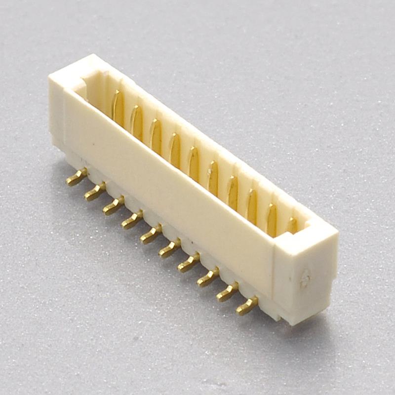
Figure 5 — KR0800 straight (180°) SMT wafer, top entry Right-angle wafer (90° / side entry)
0.8mm pitch, single row, 2–20 circuits, 30V, 0.5A. Side-entry SMT shrouded header. This is the configuration that delivers the 1.75mm mounted height.
IDC housing
0.8mm pitch, single row, 2–20 circuits, 30V, 0.5A. The wire-side body that makes the insulation displacement joint and latches to the wafer.
Full series documentation
- KR0800 series engineering drawing (PDF)
- KR0800 product specification (PDF)
- KR0800 package specification (PDF)
Circuit Count Range and PCB Layout Considerations
The KR0800 covers 2 through 20 circuits in a single row. The table below gives the contact-field width for common configurations, calculated from the 0.8mm pitch.
Total circuits Pin-field width (calculated from 0.8mm pitch) 2 0.80mm 3 1.60mm 4 2.40mm 5 3.20mm 6 4.00mm 8 5.60mm 10 7.20mm 12 8.80mm 14 10.40mm 16 12.00mm 20 15.20mm How to read this table. Width = (N − 1) × 0.8mm, where N is the circuit count. This is the distance across the contact field only — not the overall wafer or housing outline, which adds shrouding and solder tab geometry on top.
Overall dimensions, the SMT pad pattern, solder tab positions, and stencil recommendations must come from the KR0800 product drawings and the series engineering drawing linked above, or be requested from KONNRA engineering for your specific circuit count and entry direction.
The KONNRA 0.8mm Pitch Connector Family
Series Type Circuits Current Voltage Rows KR0800 SUR IDC, wire-to-board 2 – 20 0.5A 30V Single KR0802 Board-to-board SMT 2×2 – 2×26 1A 100V Dual KR0803 Wire-to-board 2 – 20 0.5A 30V Single QZ000372 FPC plug 12 pin 2A — Single QZ000373 FPC receptacle 24 pin 2A — Single 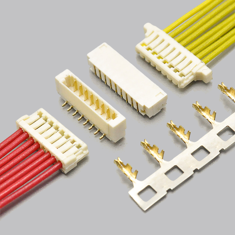
Figure 6 — KONNRA KR0803 0.8mm pitch electrical connector, a wire-to-board option in the same pitch class Decision rule: need a removable cable on an ultra-low board → KR0800. Need a fixed board-to-board stack in the same pitch class → KR0802. Need a flat flexible cable → QZ000372 / QZ000373.
Explore the full 0.8mm pitch range
Applications and Cable Assembly Options
Compact pitch plus IDC termination suits products where the harness is short, the wire is fine, and the enclosure is shallow.
Application Why the KR0800 fits Automotive electronics Low-profile in-cabin and sensor modules; −40°C to +105°C rating; supported by IATF16949 and LV214 / US CAR-2 qualified automotive series Communications and networking Dense board-to-module wiring in routers, edge devices, and antenna modules Consumer electronics Camera modules, wearables, and slim handheld devices where 1.75mm mounted height is the deciding constraint Medical devices Compact internal wiring, supported by KONNRA’s ISO13485 medical device quality system Industrial control Sensor and signal wiring in confined enclosures Battery and power modules Signal and sense lines alongside discrete power conductors Cable assembly options
KONNRA builds cable assemblies on the KR0800 system in the standard harness configurations:
Cable type Description Typical use Single-headed IDC housing on one end, bare wire leads on the other Pigtail to a wafer, panel wiring Same-side-head Housing on both ends, same orientation Board-to-board extension, same-direction routing Reverse-side-head Housing on both ends, reversed orientation Board-to-board extension, reversed routing Cable assemblies are produced in KONNRA’s wiring harness division, which accounts for 40% of company sales and operates its own injection moulding and assembly workshops. Connector lead time is typically 2–3 weeks; wiring harness lead time is typically 3–4 weeks.
Explore KONNRA wiring harness capabilities
Why Source JST SUR 0.8 Connectors from KONNRA
Dongguan Konnra Electronics Co., Ltd. (brand: KONNRA) was founded in 2004 and is a National High-Tech Enterprise specialising in connector and wiring harness research, development, production, and sales.
Manufacturing depth. A vertically integrated process covering precision mould design and manufacturing, automation design, precision injection moulding, stamping, assembly, and CCD visual inspection. Automation coverage exceeds 95% across production lines.
Testing and validation. A CNAS-accredited laboratory with 45+ sets of precision testing instruments, and CAE analysis — contact nonlinear analysis, material nonlinear analysis, motion simulation, thermal field analysis, and high-frequency analysis — performed in Ansys 2022 R1. Verification data is available on request.
Inspection coverage. Full-line intelligent visual CCD inspection covers 95% of production processes, using Mitsubishi and Panasonic PLC control systems with FA25–35mm optical lenses and 5-megapixel cameras. Automotive connector series receive 100% CCD visual inspection.
Quality systems. ISO9001, ISO14001, IATF16949, ISO45001:2018, ISO13485, IPC620, and UL product and operational safety certifications, with automotive-grade series additionally certified to LV214 and US CAR-2.
Capacity and delivery. Production bases in Dongguan Wangniudun (30,000 m², 350+ employees), Dongguan Changan (10,000 m², 150+ employees), and Hunan Daoxian (2,600 m², 100+ employees), with regional offices in Beijing, Chongqing, Hunan, Shanghai, and Kunshan. Key materials are prestocked, and complete connector set samples can be delivered within 45 days. KONNRA reported 2025 sales of RMB 310 million, with connectors at 60% and wiring harnesses at 40% of the product mix, and has served global cooperative clients including BYD, Volkswagen, and DJI.
Custom and joint R&D. Where a standard 0.8mm part does not fit — an unusual circuit count, a specific mounting height, or a material requirement — KONNRA supports customer joint R&D customisation.
Frequently Asked Questions
What is a JST SUR 0.8 connector?
The JST SUR 0.8 is a 0.8mm pitch, single-row, wire-to-board insulation displacement (IDC) connector with SMT mounting and a friction lock. It is rated 0.5A AC/DC at 30V with AWG #32 wire, derated to 0.2A with AWG #36, and is available in 2 to 22 circuits. A side-entry version measures 1.75mm high and 3.9mm deep after mounting. The KONNRA KR0800 series is documented as its cross-reference equivalent.
What is an insulation displacement connector?
An insulation displacement connector forms its electrical joint by pressing an unstripped wire into a contact slot narrower than the conductor, so the slot cuts through the insulation and wipes the copper. No stripping and no crimping are involved. At 0.8mm pitch this is the practical route, because AWG #36 and #34 conductors are too fine to crimp repeatably.
Does the JST SUR need a crimping tool?
No. The SUR terminates by pressing the wire into the IDC housing, so the required tooling is a hand press or benchtop IDC tool rather than a crimp tool and die set. JST does offer a separate SUH crimp-style connector for the same application class if you specifically need crimp termination.
What is the KONNRA equivalent of the JST SUR 0.8?
The KONNRA KR0800 series — a 0.8mm pitch single-row SUR IDC wire-to-board connector covering 2–20 circuits at 0.5A and 30V. It comprises a straight wafer, a right-angle wafer, and an IDC housing, with gold-over-nickel plating.
What wire gauge does the JST SUR 0.8 use?
JST documents the SUR for AWG #36, #34 and #32, with an insulation outside diameter of about 0.39mm. Current rating is 0.5A with AWG #32 and 0.2A with AWG #36. KONNRA’s KR0800 series documentation references AWG #32 — confirm your specific conductor size against the product specification if you intend to use #34 or #36.
What is the current rating of the JST SUR 0.8?
0.5A AC/DC with AWG #32 wire and 0.2A AC/DC with AWG #36 wire, at a rated voltage of 30V AC/DC. The KONNRA KR0800 is documented at 0.5A and 30V. Note that the derating is driven by conductor size, not by the contact — if your design is near the limit, specify the wire first.
How much board space does 0.8mm pitch save?
A side-entry JST SUR measures 1.75mm mounted height and 3.9mm depth, and occupies approximately 34% less board area than a comparable 1.0mm pitch connector. Top-entry SUR trades that around: 3.9mm height, 2.2mm depth.
Can the JST SUR be placed with a standard SMT vacuum nozzle?
Yes. The SUR shrouded header is designed with no holes in the shroud, so vacuum from a pick-and-place nozzle cannot leak through it. That means the part can be placed with the same nozzle used for the rest of the SMT line, without a special nozzle or tape-and-reel change.
Does the JST SUR 0.8 have a through-hole version?
No. Both the JST SUR and the KONNRA KR0800 are SMT-only systems, in side-entry and top-entry (or straight and right-angle) configurations. There is no through-hole option at this pitch.
What is the operating temperature range?
JST documents the SUR at −25°C to +85°C. The KONNRA KR0800 is documented at −40°C to +105°C, which is relevant for automotive, outdoor, and thermally cycled equipment.
What is the difference between the JST SUR and the JST SR?
Both are 0.8mm pitch families, but they are different series with different housings and headers, and they do not mate with each other. When sourcing a replacement, cross-reference on the specific part number — for example a 12-circuit AWG #32 SUR part (12SUR-32S) — rather than on “0.8mm JST”.
How long does it take to get samples?
KONNRA can deliver complete connector set samples within 45 days. Connector production lead time is typically 2–3 weeks and wiring harness lead time typically 3–4 weeks.
Request a Quote, Sample, or Cross-Reference Verification
KONNRA supplies the KR0800 series as individual components or as complete pre-terminated cable assemblies.
- Request a quote — KR0800 pricing, MOQ, and configuration options
- Request a sample — complete connector set samples within 45 days
- Request cross-reference verification — confirm KR0800-to-JST SUR 0.8 equivalence for your specific circuit count and wire size
- Request drawings — series engineering drawing, product specification, and package specification
Contact KONNRA Electronics
- Phone: (86)-769-85449875
- Email: info@konnra.com
- Address: No.6 Nanchang South Road, Chijiao, Wangniudun, Dongguan, Guangdong, China
- Contact us
Sources. JST SUR series specifications are taken from JST’s published product data for the SUR series (pitch, circuit counts, current and voltage ratings, temperature range, conductor size, insulation O.D., insulation resistance, withstanding voltage, mounting direction, lock type, and standards). KONNRA KR0800 specifications are taken from KONNRA’s published product and component documentation for the KR0800 series. Where the two sources do not agree, the difference is called out in the specification section above. Always confirm final dimensional and electrical requirements against the current manufacturer drawing for your specific part number.
https://konnra.com/jst-sur0-8-connector-complete-guide/
Dongguan Konnra Electronics Co., Ltd -
AuthorPosts

- You must be logged in to reply to this topic.